Category Archives: arduino

Asip now available through Arduino Library Manager

As you probably know if you have read this blog before, Asip is a protocol to control an Arduino board from a computer. The protocol is intended to be a more extensible replacement for Firmata. The idea is that you can control the board directly from a USB or network connection by means of simple plain text messages, such as I,p,13,1 to set pin 13 to high.

From today, installing Asip on an Arduino board is much simpler:

  • Make sure that the version of your Arduino IDE is at least 1.6.2 and open it.
  • Click on Sketch -> Include Libraries -> Manage Libraries to open the library manager.
  • Type asip in the search box and you should get something similar to the following imageArduino library manager for Asip
  • Click on the first link for simple I/O services (you can add support for additional services later with the second link).
  • Click on File -> Examples -> asip and open AsipIO.
  • Connect your board, upload the sketch and you are ready to go.

If you want to use servo motors, sonar distance sensors and piezo tones, in addition to the plain asip library install also the library asip-additional-services and check the examples.

We have developed client libraries in Racket, Java and Python. Contact me if you need additional details, we will try to add tutorials and further documentation as soon as we have time.

Controlling an Arduino board via USB with the ASIP protocol

mirtoLast year we built the Middlesex Robotic Platform (MIRTO) using a Raspberry Pi and an Arduino Uno board. In our configuration the Arduino board is essentially a “slave” of the Raspberry Pi. A pair of HUB-ee wheel, infra-red sensors and bumper sensors are attached to the Arduino board, but all the “logic” is on the Raspberry Pi. It is the Raspberry Pi that sends the instructions to read the IR values and to set the speed of the wheels. In our configuration, the Arduino board is attached to the Raspberry Pi using a serial connection (GPIO pins on the Raspberry Pi and pin 0 and 1 on the Arduino). In MIRTO we installed Firmata on the Arduino board and we extended Firmata clients available on the Raspberry Pi. More precisely, we had to extend Firmata with specific messages for wheels (both directions: to set the speed and to read quadrature encoders) and for all the other extensions we wanted to use, such as sonar distance sensors. I think that protocols of this kind can open a lot of opportunities, by allowing the integration of platforms such as Raspberry Pi and possible multiple Arduino boards.

However, we soon realised that Firmata is not as easy to extend as we wanted, in particular it may be difficult to add one of the many available Arduino libraries for things such as NeoPixels etc.. We also found the 7-bit message encoding of Firmata messages error prone (in the sense that our code had a lot of bugs :-). For these reasons, Michael Margolis suggested the implementation of a new, simpler protocol. We wanted the protocol to be text-based and to allow easy integration of new services. We have now a working implementation of this protocol that we called the Arduino Service Interface Protocol (ASIP). Michael has developed the Arduino code, which is available at this link:

We have then written client libraries for:

(and we are working at a Python implementation).

The current implementation uses serial communication, but Michael Margolis has designed the protocol so that it can be very easily adapted to any form of streaming communication.

OK, let’s see some practical details. First of all, a quick overview of the installation process:

  1. Download the code available at https://github.com/michaelmargolis/asip; you will see that there are two directories: documents/ and asip/
  2. Copy the directory asip/ (not documents) to the library folder of your Arduino IDE. If you don’t know where this folder is, check Manual Installation at this link http://arduino.cc/en/Guide/Libraries
  3. Restart your Arduino IDE. At this point, if you click File -> Examples, you should see an asip menu. Select AsipIO to install a simple ASIP Input/Output configuration. This will allow you control digital and analog pins.
  4. Connect an Arduino board, upload the code, open the serial monitor and check that you are receiving regular message of the form
    @I,A,{...}

    (these are the analog values of analog pins).

If everything is OK on the Arduino side, you can now play with one of the libraries available. As an example, I’m going to show you how to use the Java library available at https://github.com/fraimondi/java-asip. Clone the repository and open one of the examples, for instance src/uk/ac/mdx/cs/asip/examples/SimpleBlink.java. The code is the following:

package uk.ac.mdx.cs.asip.examples;
 
import uk.ac.mdx.cs.asip.AsipClient;
import uk.ac.mdx.cs.asip.SimpleSerialBoard;
 
/* 
 * @author Franco Raimondi
 * 
 * A simple board with just the I/O services.
 * The main method does a standard blink test.
 * We extend SimpleSerialBoard but this is not
 * strictly required for this example.
 */
public class SimpleBlink extends SimpleSerialBoard {
 
	public SimpleBlink(String port) {
		super(port);
	}
 
	public static void main(String[] args) {
 
                // You need to provide the serial port to which Arduino
                // is connected. Under Win this could be COM3 or COM4,
                // check the Arduino IDE to find out.
		SimpleBlink testBoard = new SimpleBlink("/dev/tty.usbmodem1411");
 
                // We need a try/catch block to sleep the thread.
		try {
                        // This is a simple setu-up: we request
                        // port mapping for digital ports (not strictly
                        // necessary).
			Thread.sleep(1000);
			testBoard.requestPortMapping();
			Thread.sleep(500);
                        // We then set pin 13 to OUTPUT mode and pin 2 
                        // to input (pull-up) mode, even if pin 2 will
                        // not be used and therefore we could skip this.
			testBoard.setPinMode(13, AsipClient.OUTPUT);
			Thread.sleep(500);
			testBoard.setPinMode(2, AsipClient.INPUT_PULLUP);
			Thread.sleep(500);
		} catch (InterruptedException e) {
			e.printStackTrace();
		}
		while(true) {
                        // As above, we need a try/catch block to sleep.
                        // Then, we just loop forever, turning on and off
                        // a LED attached to pin 13.
			try {
				testBoard.digitalWrite(13, AsipClient.HIGH);
				Thread.sleep(2000);
				testBoard.digitalWrite(13, AsipClient.LOW);
				Thread.sleep(500);
			} catch (InterruptedException e) {
				e.printStackTrace();
			}
		}
	}
}

The code should be pretty self-explanatory. It subclasses a class called SimpleSerialBoard (but this is not strictly necessary), then sets up the pin modes and loops forever writing HIGH and LOW to pin 13. You can explore other methods by opening the files LightSwitch.java and Potentiometer.java, showing how to read digital and analog input pins.

Before discussing how to add additional services, let’s have a look at the format of ASIP messages. Messages are ASCII messages, terminated by an end-of-line character. An example message to the Arduino board is I,P,13,1 where I is a character identifying a service (in this case, the Input/Output service), followed by an instruction to that service (in this case, P, meaning setting the value of a digital pin), followed by the pin number and by the number to be written.

Messages from the Arduino board are initiated by a special character: @ starts a standard message, ~ starts an error message, and ! starts debug/reporting messages. After this character, the message has a structure similar to the one above: a service ID, followed by a service-specific character, and then a list of parameters.

The Java library simply abstracts from these messages and provides easy to remember method names. The library creates a reading thread to manage incoming messages. This structure is the same in the Racket and Erlang clients. The key notion of ASIP is the one of a service. Example of services are a distance service, a motor service, a NeoPixel LED strip service, etc. Each service is identified by a single-character ID. For instance, a motor service has ID ‘M’, while a distance sensor has ID ‘D’, etc. If you want to implement a new service, you need to do two things:

  1. Implement code for the Arduino board.
  2. Implement code for a client library.

As an example of how to implement a new service, switch to branch neopixels on https://github.com/michaelmargolis/asip/ and open the file asip/utility/asipNeoPixels.h. This is the header file to define a new service to control a strip of NeoPixels LEDs. As you can see from the header file, we are defining a new class asipNeoPixelsClass that is a subclass of asipServiceClass. The new class needs to implement some abstract method of the superclass. In particular, it should define how to process messages directed to this class. Open the implementation asipNeoPixelsClass.cpp and check the method processRequestMsg: it shows how to process messages to set brightness, change the colour of a pixel, and show the LED strip. You decide what to implement here, and how. So far, we have IDs for specific operations that we want the service to perform, followed by optional parameters, all in the form of comma-separated values.

After defining this new service class, you should write Arduino code to instantiate this new service. For an example, open the file examples/AsipNeoPixels/AsipNeoPixels.ino. This file creates a firmware with support for standard I/O service, for a distance service attached to pin 4, and for two NeoPixels strips attached to pins 6 and 9. Essentially, this code creates the appropriate services, adds them to array of services to be added to the main loop, sets up the pins appropriately, and then loops by invoking the method service of AsipClass. This is the method that keeps reading incoming messages and dispatches them to the registered services, and also sends data from services to the serial port.

Upload the code above to the board and at this point the board should be ready to use: just send messages to the serial port with the appropriate ID and requests, and you will see pixels turning on and off. You can do this from the serial monitor, if you just want to test things. If you want to define a corresponding Java service for java-asip, have a look at the file src/uk/ac/mdx/cs/asip/services/NeoPixelService.java at https://github.com/fraimondi/java-asip/. This class extends a generic AsipService class and provides methods to read/write messages for NeoPixels services. As an example of application, check the file src/uk/ac/mdx/cs/asip/examples/SimpleNeoPixelWithDistance.java: the file shows how to initialise a board with all the required services and how to use the methods provided by NeoPixelService.java.

We have published a tool paper about ASIP, you can find it here:

As usual, drop me an email of leave a comment if you have questions..

The MIddlesex Robotic plaTfOrm: MIRTO

MIRTOMIRTO (the MIddlesex  Robotic plaTfOrm, also known as Myrtle) is an Arduino+Raspberry Pi platform currently used for teaching in the first year of the Computer Science degree at Middlesex University. It is developed as an open-source platform and the design and source code are available online (see links at the bottom of this post).

An overview of this first year has recently been given by Tony Clark at http://clarktony.blogspot.co.uk/2013/12/computer-science-approach-to-teaching.html, including  the motivations for our choice of Racket as the core programming language.

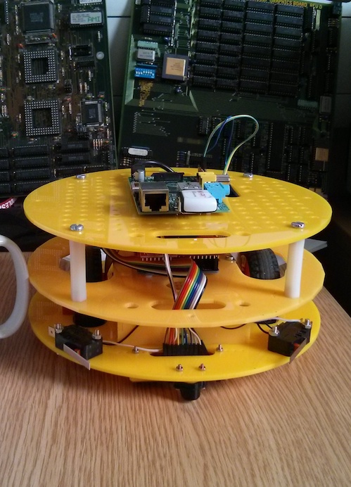
Myrtle is the main character of “block 3″ for first year Computer Science students (see previous link for an introduction to the idea of “blocks” and for an overview of our teaching and assessment strategy). The structure of Myrtle is the following:

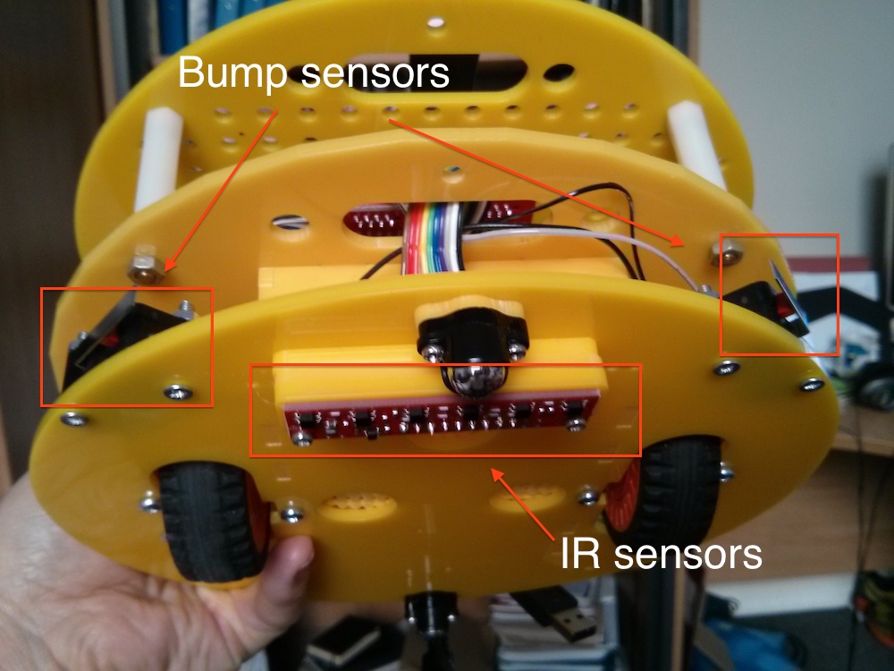
1. A base layer incorporates Infra-Red sensors, bump sensors and a pair of HUB-ee wheels (see figure below):

sensors

 2. In the center, an Arduino Uno collects the data from the sensors and is connected to the wheels to drive them (see figure below): arduino-layer

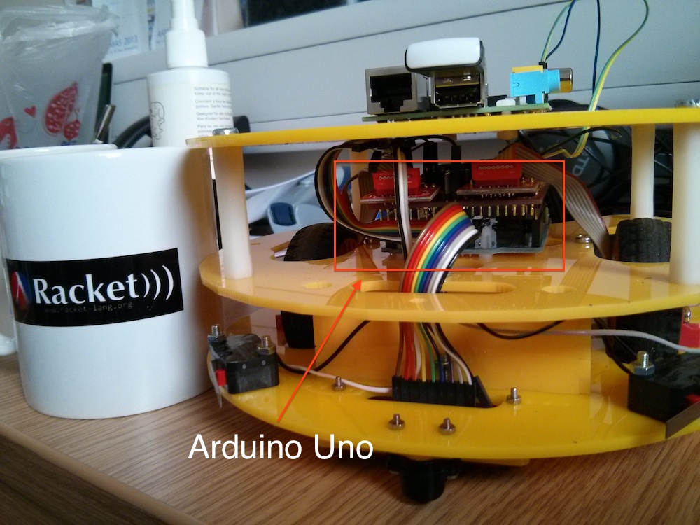
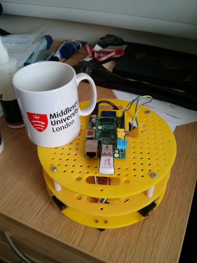
3. The top layer for Computer Science students is a Raspberry Pi that is connected to the Arduino Uno board by means on a serial connection on the GPIO pins (a WiFi USB dongle is also visible in the figure below).

IMG_20140204_152433

This is a very flexible platform: Engineering students will employ mainly the Arduino layer (possibly two Arduino layers, one on top of the other) together with the Arduino IDE. Computer Science students will work mainly at the Raspberry Pi level, possibly extending the core platform with additional features (USB cameras, a fourth layer on top, etc.). More importantly, the platform offers a number of opportunities for teaching core Computer Science notions: from product of finite state machines to concurrency and synchronisation when reading the encoders, from networking at all levels (IP, TCP, applications) to data structures, functional programming, etc.

The software architecture of the platform for Computer Science students involves:

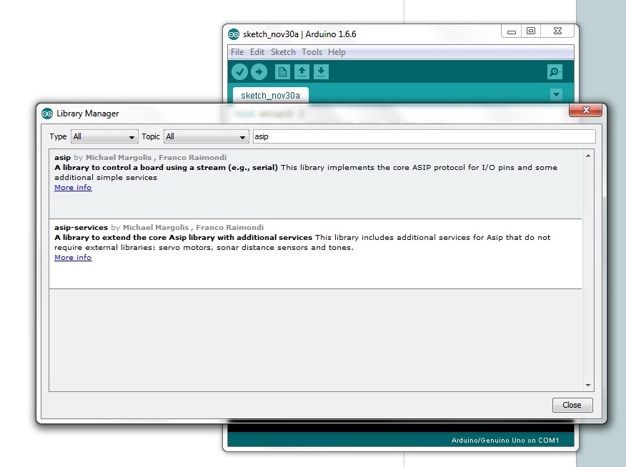
  1. A modified version of Firmata running on the Arduino Uno. This is an extension of Standard Firmata developed by Michael Margolis, the author of various books including the “Arduino Cookbook” and currently at Middlesex University.
  2. A Racket Firmata module extended with SysEx messages and other features used in Myrtle. This version works on Windows, Linux and Mac and detects the operating system automatically, together with the port to which the Arduino is attached.
  3. A Racket module (MIRTOlib.rkt) to interact with Myrtle using the Firmata library described above.

The following is an overview of block 3 for first year Computer Science students:

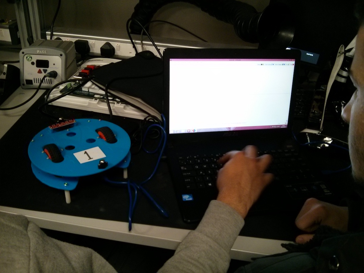
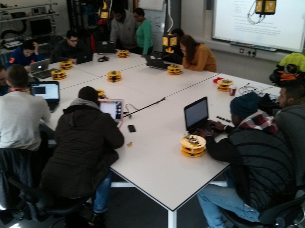
The students are initially exposed to the Arduino layer only to familiarize with MIRTOlib.rkt. In the figure below, Myrtle is provided without the Raspberry Pi layer and is connected directly to a PC or laptop using a USB cable. We employ this configuration to reason about interaction between components (wheels and sensors) using finite state machines, use cases, statecharts and sequence diagrams. We also have a local installation of MediaWiki for students so that they can document their progress using wiki pages they create. In the picture below, DrRacket is running on the PC/laptop and the Arduino layer of Myrtle is connected using a USB cable:

arduino-layer

Teaching then moves to networking, introducing IP addressing, TCP and network applications. The main result is an HTTP server built in Racket that can control an Arduino board using Firmata to turn on and off LEDs. The following is an example handout for the students addressing the HTTP server in Racket, starting from unquote + splicing, then moving to xexpr and finally to the actual HTTP server (click on the link to download the PDF):

A simple HTTP server in Racket (PDF)

In parallel, we start introducing some basic functions provided by MIRTOlib.rkt so that the students can move the wheels and read bump and IR sensors.

We then move to introducing a new architecture and a new operating system: Raspberry Pi  (ARM) and Linux. At this point we add the third layer to Myrtle and we “detach” the robot from the PC/laptop. We now access the robot over a wireless connection on the Raspberry Pi, where students upload Racket code and run it from the command line.

myrtlelab-top

The material now asks the students to reason about control . For instance, students are asked to print the IR sensors every 2 seconds and to move the wheels for 2 rotations, stopping immediately if one of the bump sensors is activated. In parallel, student learn how to read and post tweets using the Twitter API from Racket and they study encryption algorithms, authentication mechanisms and, in particular, OAuth 1.0 for Twitter.

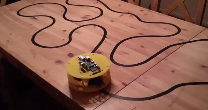
Finally, students have a go at “control theory” with the problem of line following. This gives us a chance to talk a little bit about calculus (derivation and integration) to build a PID controller for the robot (click on the image for a video about this, available at http://www.youtube.com/watch?v=laafaTZ7mDU).

linefollowing

In the last two weeks the students will split into groups and will work on a project of their choice. Ideas include a web interface to drive the Myrtle wireless, control via majority voting using Twitter, advanced line following in various conditions, dancing robots, etc. I will provide additional details at the end of this block, together with the Racket code for line following and other examples: I don’t want to publish it now because students need to find it on their own!

So far, the results are very encouraging: we are nearly at the end of the course, with only 6 weeks left, and attendance is regularly above 90% (yes, this is 90% for all lab sessions in a cohort of approximately 120 students). Students are engaging with the material and it is common to see students remaining in the labs well after the end of the sessions.

Setting up this block has required a lot of preparation work by a number of people. Apart form all the academics and teaching assistants from the Computer Science department, we had enormous help from Michael Margolis, Puja Varsani and Nick Weldin.

In terms of practical issues:

  • So far, the robots seem to cope well with students using them, no major hardware failure reported in nearly 5 weeks of continuous usage. We have approximately 20 robots and we typically use 7 or 8 of them per session (each session is attended by approximately 20 students).
  • We have approximately 20 battery banks (9000 mAh), which are enough to go through a day of sessions. The batteries are recharged overnight.
  • Every week we provide a set of SD cards for the Raspberry Pi, setting up an environment with Racket and all the additional software required (voice recognition and image capture, for instance)

The source code for this platform is available at:

  • https://github.com/fraimondi/myrtle: Arduino code for the Arduino Uno layer (modified Firmata), MIRTOlib.rkt and some simple testing functions. Design files will be added very soon.
  • https://bitbucket.org/fraimondi/racket-firmata: platform-independent (in the sense that it seems to work well in Linux, Mac and Win) Firmata client for Racket. We have tested it with “standard” boards and it seems OK, even without Myrtle.
  • We also have an SD card image ready that includes Racket 5.3.6 pre-compiled. Send me an email if you want one of these.

Feel free to contact me if you need additional details!

The classic Simon memory game in Racket + Arduino

OriginalSimon

(Source: Wikipedia)

The Simon memory game is one of the first electronic games I remember from my childhood, together with late 70′s Atari consoles and early 80′s  Game & Watch Nintendo handheld (Donkey Kong was my favourite).

The game is very simple: there are four coloured buttons that correspond to four different tones. The game presents a sequence of colours and the player has to repeat the sequence. If the player is successful, a further colour is added, otherwise a horrible 42 Hz saw-shaped sound is emitted; check this commercial http://www.youtube.com/watch?v=yF0ZUXclW8Y

It is not difficult to implement the game in Racket using an Arduino UNO board with four LEDs and four digital buttons, connected using Firmata.

IMG_20131207_074841I have connected the LEDs to PINs 8, 9, 10 and 11; I have connected the buttons to PINs 2, 3, 4 and 5. The figure on the left shows the spaghetti-like circuit. If you want to see what happens when you run the code, have a look at this link of my daughter playing with it: http://youtu.be/tk69MUwQs5A (in Italian with some subtitles…)

This game is very interesting for teaching purposes: it is easy enough to be covered in a session, but it also contains some issues that are not so simple, such as distinguishing between a state in which the code displays the sequence from a state in which the player is entering the sequence. The sequence is not fixed and it needs to be reset when the player makes a mistake. One exercise I will do in class is to ask the students to write down all the possible states and the possible transitions.

Let’s now  have a look at a possible Racket code for this. I assume you have Firmata installed on your Arduino UNO and you also know how to connect it to Racket using Firmata to read a button. If this is not the case, it is probably better if you have a look at this other link before proceeding: http://www.youtube.com/watch?v=7Zzh7qrQph4. I start with

The following is the description of a possible Racket implementation of the game; it is available with sound files and firmata at this link: http://www.rmnd.net/racket/simon. The implementation could be improved in a number of ways, see at the bottom of this post for a list of tasks for students. I start by including the appropriate Firmata module and by declaring the PINs to which the LEDs and the push buttons are connected to. I then define two lists that I use in other places in the code to initialise the PINs and to do boot sequences.

;; change as appropriate for your OS
(require "firmata-mac.rkt")
 
(define yellow 8)
(define green 9)
(define red 10)
(define blue 11)
 
(define in-yellow 2)
(define in-green 3)
(define in-red 4)
(define in-blue 5)
 
(define colours (list yellow green red blue))
(define in-colours (list in-yellow in-green in-red in-blue))

To keep track of the various buttons being pressed, I extend the code at http://www.youtube.com/watch?v=7Zzh7qrQph4 defining four sets of states for the buttons (all initially UP):

(define curStateYellow "UP")
(define previousStateYellow "UP")
 
(define curStateGreen "UP")
(define previousStateGreen "UP")
 
(define curStateRed "UP")
(define previousStateRed "UP")
 
(define curStateBlue "UP")
(define previousStateBlue "UP")

I then declare a list that I use to store the sequence of states to be guessed with
(define seq '()). The key idea of the game is to use “states” to keep track of what the code should do. We start from a state “gameOver”, declaring it with (define state "gameOver").
I then declare a few support functions, see comments in the code below:

;; Show a sequence of colours: switch on a PIN, play the
;; corresponding sound with play-index (see below), clear
;; the PIN, wait 0.2 seconds and then call itself recursively until
;; there is something to show.
(define (showSeq s)
  (cond ( (> (length s) 0)
          (set-arduino-pin! (first s))
          (play-index (first s))
          (clear-arduino-pin! (first s))
          (sleep 0.2)
          (showSeq (rest s))
          )
        )
  ) ;; end of showSeq
 
;; play a note using its position in the list (yellow - green - red - blue)
;; (see below the definition of play)
(define (play-index i)
  (cond ( (= i yellow) (play "yellow"))
        ( (= i green) (play "green"))
        ( (= i red) (play "red"))
        ( (= i blue) (play "blue"))
        )
)
 
;; play a sound with afplay (works on a mac)
;; in Linux, you can use aplay.
;; It just calls a command-line using system
(define (play note)
  (system (string-append "afplay " note ".wav &"))
  )
 
;; This is used to set-up the mode of the various PINs. I do
;; so using the high-order function map, together with a lambda
;; function
(define (setup)
  (map (λ (i) (set-pin-mode! i OUTPUT_MODE)) colours)
  (report-digital-port! 0 1)
  (map (λ (i) (set-pin-mode! i INPUT_MODE)) in-colours)
)

The core of the code is the function mainLoop that loops through the following sequence of states (code below, after this list):

  • gameOver: this is either the initial state or the state following a wrong choice by the player. In this state we clear the sequence of colours and we generate a new random initial colour. After gameOver the code shows (and play with sounds) the sequence to the player.
  • After showing the sequence, the code moves to state playing. In this state we go through a new loop, see playingLoop below.
  • The code exits playingLoop either when the player guesses all the sequence correctly or when the player makes a mistake. In the former case the code enters a state called “correctSequence”; in the latter it enters a state called “wrongChoice”.
  • In state “correctSequence” the code adds a new colour to seq and then shows the sequence. It then goes back to state “playing”.
  • In state “wrongChoice” the code moves to gameOver and repeats the loop.

This is the full code for the function:

(define (mainLoop)
 
  (cond ( (equal? state "gameOver")
          (printf "DEBUG: Current state is gameOver\n")
          ;; If we are in game over, we clear the sequence, we add
          ;; a random value and we set state to "playing"
          (set! seq '())          
          (set! seq (append seq (list (list-ref colours (random (length colours))))))
          (sleep 0.5)
          (set! state "showSequence")
          )
 
        ( (equal? state "showSequence")
          (printf "DEBUG: Current state is showSequence\n")
          ;; We show the sequence and then we enter playing
          (sleep 0.3)
          (set! state "playing")
          (showSeq seq)
          )
 
        ( (equal? state "playing")
          (printf "DEBUG: Current state is playing\n")
            ;; We enter the main playing loop, see below (player does things)
           (playingLoop seq)
        )
 
        ( (equal? state "wrongChoice")
          ;; The player has made a wrong choice:
          ;; we enter game over state
          (sleep 0.5)
          (set! state "gameOver")
          )
 
        ( (equal? state "correctSequence")
          (set! seq (append seq (list (list-ref colours (random (length colours))))))
          (sleep 0.5)
          (showSeq seq)
          (set! state "playing"))
  )
  (mainLoop) ;; call recursively
) ;; end of mainLoop

The player interacts with the push buttons in the playingLoop function. The function takes in input a sequence (of colours) and expects that the player presses the first colour in the list. If this is the case, it calls itself recursively on the tail of the sequence of colours. Otherwise, it sets state to “wrongChoice” and plays the horrible 42 Hz sound. The code is a simple extension of the code described in FIXME to 4 buttons. The full code is the following:

;; The playing loop: the player has to guess the sequence s, we call ourselves
;; recursively on s.
(define (playingLoop s)
 
  ;; to keep track of a correct choice, used to loop at the end
  (define correct "")
 
  (cond ( (= (length s) 0)
          ;; if the list is empty, we guessed all the colours correctly!
          (set! state "correctSequence")
          (printf "DEBUG: well done, the sequence is correct!\n")
          )
        (else 
         ;; There are more colours to be guessed, we keep looping here
         ;; recording what is being pressed
         (cond ( (is-arduino-pin-set? in-yellow) (set! curStateYellow "DOWN"))
               (else (set! curStateYellow "UP")))
         (cond ( (is-arduino-pin-set? in-green) (set! curStateGreen "DOWN"))
               (else (set! curStateGreen "UP")))
         (cond ( (is-arduino-pin-set? in-red) (set! curStateRed "DOWN"))
               (else (set! curStateRed "UP")))
         (cond ( (is-arduino-pin-set? in-blue) (set! curStateBlue "DOWN"))
               (else (set! curStateBlue "UP")))
 
         ;; switch on the lights and check if it is correct when we release
 
         ;; Blue
         (cond ( (and (equal? curStateBlue "DOWN") (equal? previousStateBlue "UP")) 
                 (printf "DEBUG: blue pressed\n")
                 (set-arduino-pin! blue)
                 (play "blue")
                 ))
         (cond ( (and (equal? curStateBlue "UP") (equal? previousStateBlue "DOWN")) 
                 (printf "DEBUG: blue released\n")
                 (clear-arduino-pin! blue)
                 (cond ( (= (first s) blue) 
                         ;; the player chose the right colour
                         (set! correct "T")
                         )
                       (else (set! correct "F"))
                       )                       
                 )
         ) ;; end of blue button released
        ;; You need to repeat the code above for the three remaining colours,
        ;; see source code available on-line at the link below.
         ;; Setting the previous states
         (set! previousStateBlue curStateBlue)
         (set! previousStateRed curStateRed)
         (set! previousStateGreen curStateGreen)
         (set! previousStateYellow curStateYellow)
         (cond ( (equal? correct "T") 
                 (playingLoop (rest s)))
               ( (equal? correct "F") 
                 (set! state "wrongChoice")
                 (printf "DEBUG: ops, wrong choice!\n")
                 (play "wrong"))
               (else (playingLoop s))
         )
         ) ;; end else (sequence not empty)
        ) ;; end cond
)  ;; end playingLoop

This completes more or less the code. There are other minor things that could be added, see the code available online at http://www.rmnd.net/racket/simon. You can launch the code by setting the appropriate port for Firmata. I have run this code both on a Mac laptop and on a Raspberry Pi and it works fine. I have not tried Windows… let me know if it works for you.

Possible tasks for students:

  • A lot of code is repeated, for instance in playingLoop. Improve it by reducing the amount of duplicated code.
  • Calling OS instructions using (system ) causes the code to stop while the command is being executed because it is a synchronous call. Implement system calls using (process ). You need to manage timing for this is a different way…
  • In the original Simon game, the timing between different colours / sounds in the presentation state as you progress with levels. Modify the code to take this into account.
  • Introduce a winning state, e.g., if the player can guess a sequence of 15 colours.
  • Save best scores, or publish them on-line (Twitter, Facebook, Google+)

Speech recognition on Raspberry Pi with Sphinx, Racket and Arduino

IMG_20131112_112628 copyIn this post I put together a number of things to control two LED from a Raspberry Pi with voice recognition (via Sphinx), Firmata and Arduino. Before you start, you may want to have a look at this other post on how to connect a Raspberry Pi and an Arduino board using Firmata and Racket: http://jura.mdx.ac.uk/mdxracket/.

First of all, we need to install PocketSphinx on Raspberry Pi to do speech recognition. I am using a standard USB camera with microphone (supported by Raspberry Pi) and I’m following the instructions available here: https://sites.google.com/site/observing/Home/speech-recognition-with-the-raspberry-pi. In essence, this is what I’ve done (as root on the Raspberry Pi), please see the link above for additional details:

apt-get install rpi-update
apt-get install git-core
rpi-update

-> Connect your USB microphone (or camera+mic) and
-> reboot the RPi at this point

vi /etc/modprobe.d/alsa-base.conf 

# change as follows:
# Comment this line
# options snd-usb-audio index=-2
# and add the following:
options snd-usb-audio index=0

-> close the file and reload alsa:

alsa force-reload

wget http://sourceforge.net/projects/cmusphinx/files/sphinxbase/\
0.8/sphinxbase-0.8.tar.gz/download
mv download sphinxbase-0.8.tar.gz
wget http://sourceforge.net/projects/cmusphinx/files/\
pocketsphinx/0.8/pocketsphinx-0.8.tar.gz/download
mv download pocketsphinx-0.8.tar.gz
tar -xzvf sphinxbase-0.8.tar.gz
tar -xzvf pocketsphinx-0.8.tar.gz

apt-get install bison
apt-get install libasound2-dev

cd sphinxbase-0.8
./configure --enable-fixed
make
make install

cd ../pocketsphinx-0.8/
./configure
make
sudo make install

Et voila’, you are now ready to test your PocketSphinx installation. Go to pocketsphinx-0.8/src/programs and run:

./pocketsphinx_continuous

If you are lucky, you should get some text back… I don’t have space here (and time) to go into the details of (pocket)sphinx. Try some simple words and see if they are recognised. I ended up building a very very simple language model using the on-line tool at this link: http://www.speech.cs.cmu.edu/tools/lmtool-new.html. I use just “green”, “red” and “off” and they seem to work fine in spite of my Italian accent.

In the next step we need to connect the output of PocketSphinx with Racket. I do this in a very primitive way: I modify the source code of pocketsphinx_continous to output just the word that is recognised. This is very simple: just modify continous.c under pocketsphinx-0.8/src/programs, comment all the printf statement and output just the recognised word (drop me an email if you don’t know how to do this). I append a “RACKET: ” string at the beginning of the printed string to make sure that this is something I have generated. You can then run pocketsphinx and redirect the output to a file with something like:

./pocketsphinx_continuous -lm /home/pi/sphinx/simple/4867.lm \
   -dict /home/pi/sphinx/simple/4867.dic > /tmp/capture.txt

(notice that I’m using the language model + dictionary generated on-line)

Time now to go back to Racket. I assume you know how to connect a Raspberry Pi with an Arduino board and talk to it in Racket using Firmata (if this is not the case, please have a look at the instructions available at http://jura.mdx.ac.uk/mdxracket/index.php/Raspberry_Pi,_Arduino_and_Firmata). In the following Racket file I simply read the file /tmp/capture.txt and send instructions to the board according to the instructions received. If a command is not recognised, I print a message on screen. The code for this is the following:

#lang racket
(require "firmata.rkt")
 
(define green 12)
(define red 13)
 
(define in (open-input-file "/tmp/capture.txt"))
 
(define (process-input str)
  (printf "processing input ~a\n" str)
  (set! str (substring str 8))
  (cond ( (string=? (string-upcase str) "RED")
          (printf "I'm setting red\n")
          (set-arduino-pin! red)
          )
        ( (string=? (string-upcase str) "GREEN")
          (printf "I'm setting green\n")
          (set-arduino-pin! green)
          )
        ( (string=? (string-upcase str) "OFF")
          (printf "I'm clearing the PINs\n")
          (clear-arduino-pin! red)
          (clear-arduino-pin! green)
          )
        (else
         (printf "Sorry I cannot understand: ~a\n" str)
         (flush-output)
         )
  )
  )
 
(define (read-loop)
  (define str (read-line in))
  (unless (eof-object? str)
               (process-input str)
    )
  (read-loop))
 
(define (start-everything)
  (open-firmata "/dev/ttyACM0")
  (set-pin-mode! green OUTPUT_MODE)
  (set-pin-mode! red OUTPUT_MODE)
  (read-loop)
  )
 
(start-everything)

Job done. Now check that:

  • The modified version of pocketsphinx_continuous is running and redirecting the output to /tmp/capture.txt
  • Launch the file above with something like racket sphinx-arduino.rkt
  • Check that your Arduino board is connected and wired up appropriately

and you should get something like this:

http://youtu.be/XGYNRHWY4Ag

Future work:

  • I don’t think there is a need to write to a file… maybe pocketsphinx can redirect to a port and Racket can listen to it?
  • Improve the language model for a domain of your choice
  • Add a couple of speakers to the Raspberry Pi so that Racket can tell you what it is doing, if something has not been recognised, etc.