Category Archives: teaching

September 2014, new academic year!

It’s nearly the end of September and from Monday next week all students will be back, including a new class of 2014 Computer Science students. As I already wrote in the past, I remember very well my first day as a university student. Everything was new to me; I had no idea of what the content of the various courses was and I had no idea of what the world would look like at the end of my studies, or what kind of job I would do.

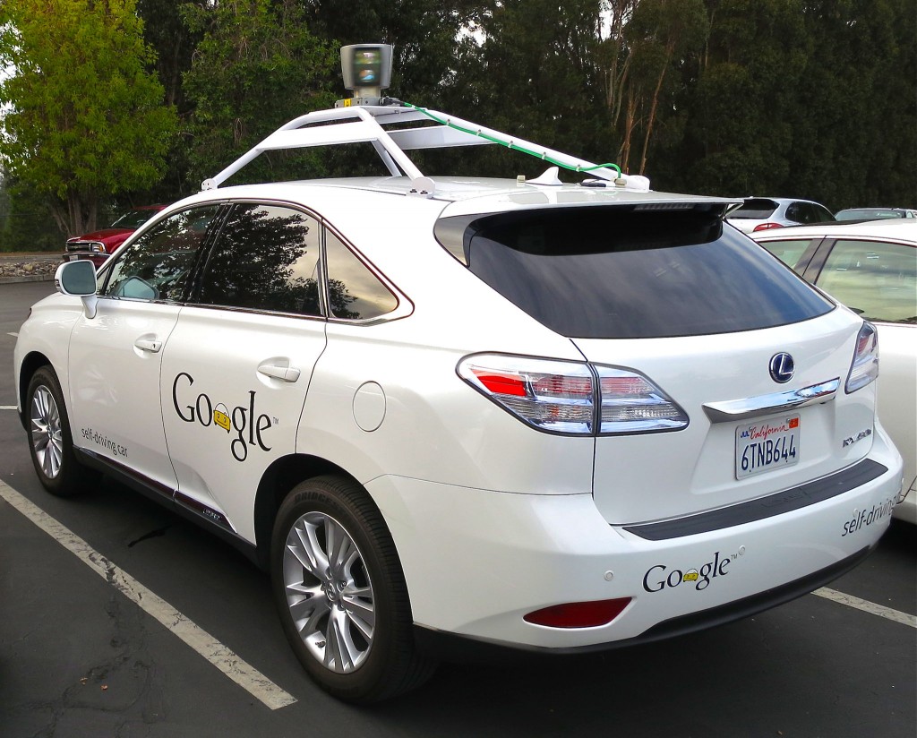
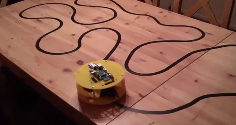
If you are a student starting on Monday, I can tell you the exact content of your courses and, given that everything is now on-line, you can also explore all the material for the year already from day 1 (don’t miss your induction week starting on Monday at 10AM in C114!). However, I’m still not able to tell you what the world will look like when you will finish your degree here at Middlesex. But one thing I know: this is probably one of the most exciting times to study Computer Science. We now have self-driving cars, like the one in the picture.

Self-driving car (Google)

Source: Wikipedia

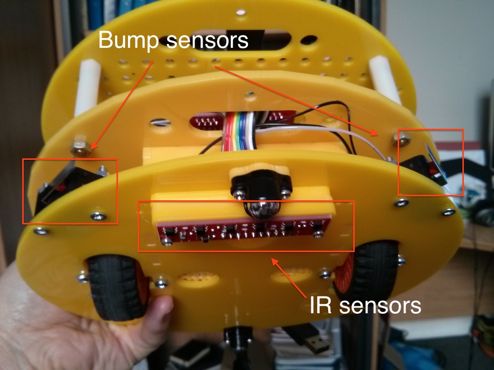
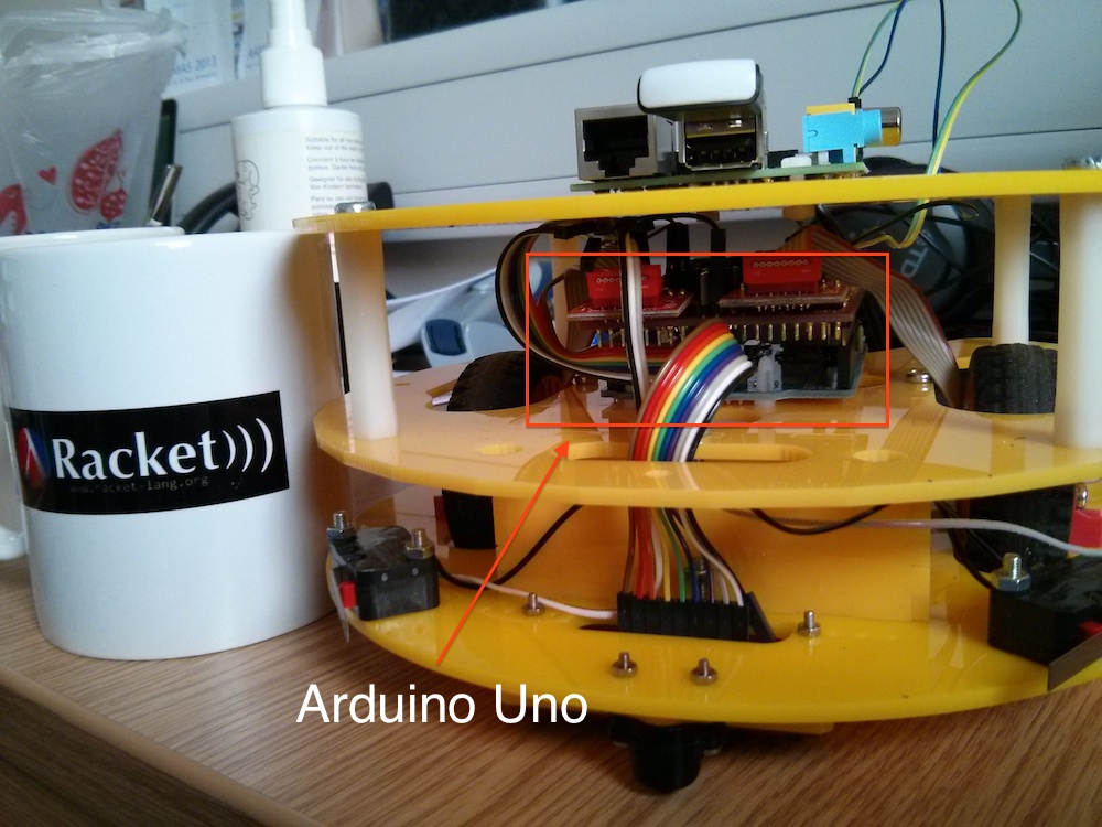
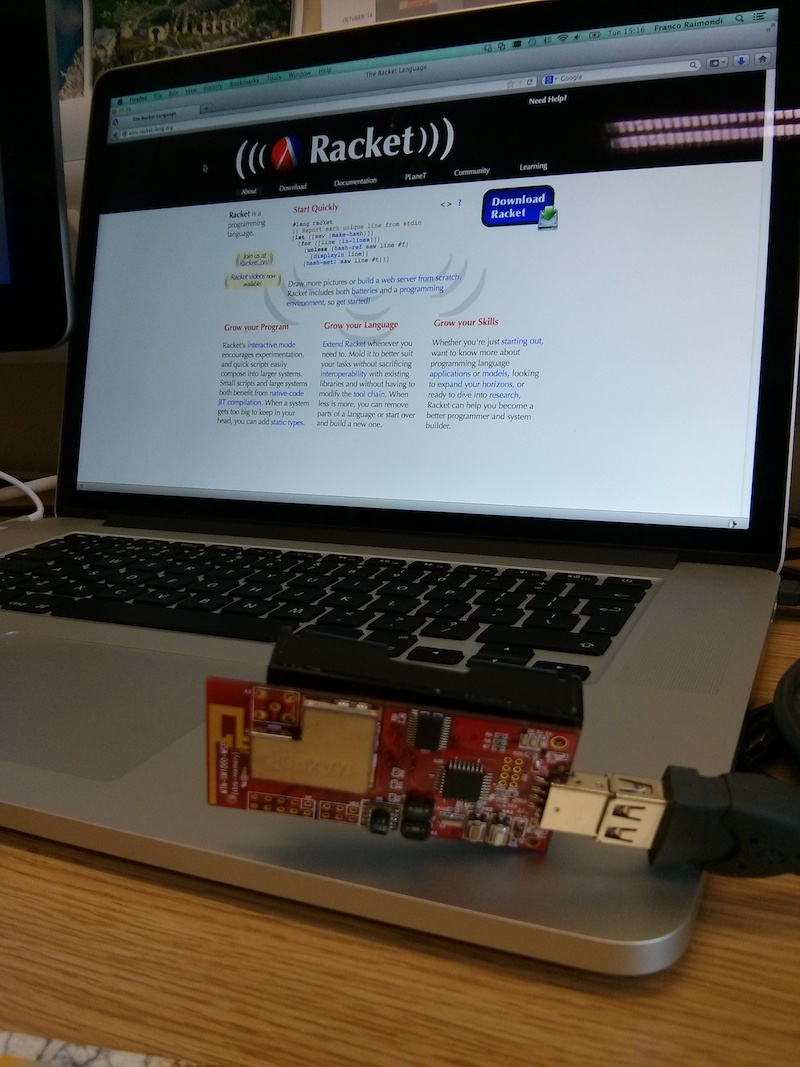
These are not prototypes that maybe we will see on our roads in ten years’ time: these cars are real. I spent a few weeks in California last month and I counted 18 self-driving cars in a single day in Mountain View. One of them gave me priority at a pedestrian crossing, autonomously. These cars are equipped with a large number of sensors, very similar to the ones that you are going to see here in your first year.

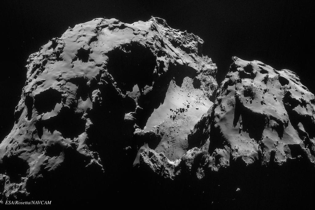
There are a number of other things that I would have considered science fiction when I started my studies: the European Space Agency is gracefully landing scientific instruments on a comet. This is a picture taken from Rosetta (see http://www.esa.int/Our_Activities/Space_Science/Rosetta):

Comet

Source: ESA

So this is what a comet looks like: very different from what I use to draw as a kid! The comet is approximately 4 km long and you can clearly see small hills and flats on it. Sometimes gas and dust are emitted (due to solar wind), and these form the visible tail.

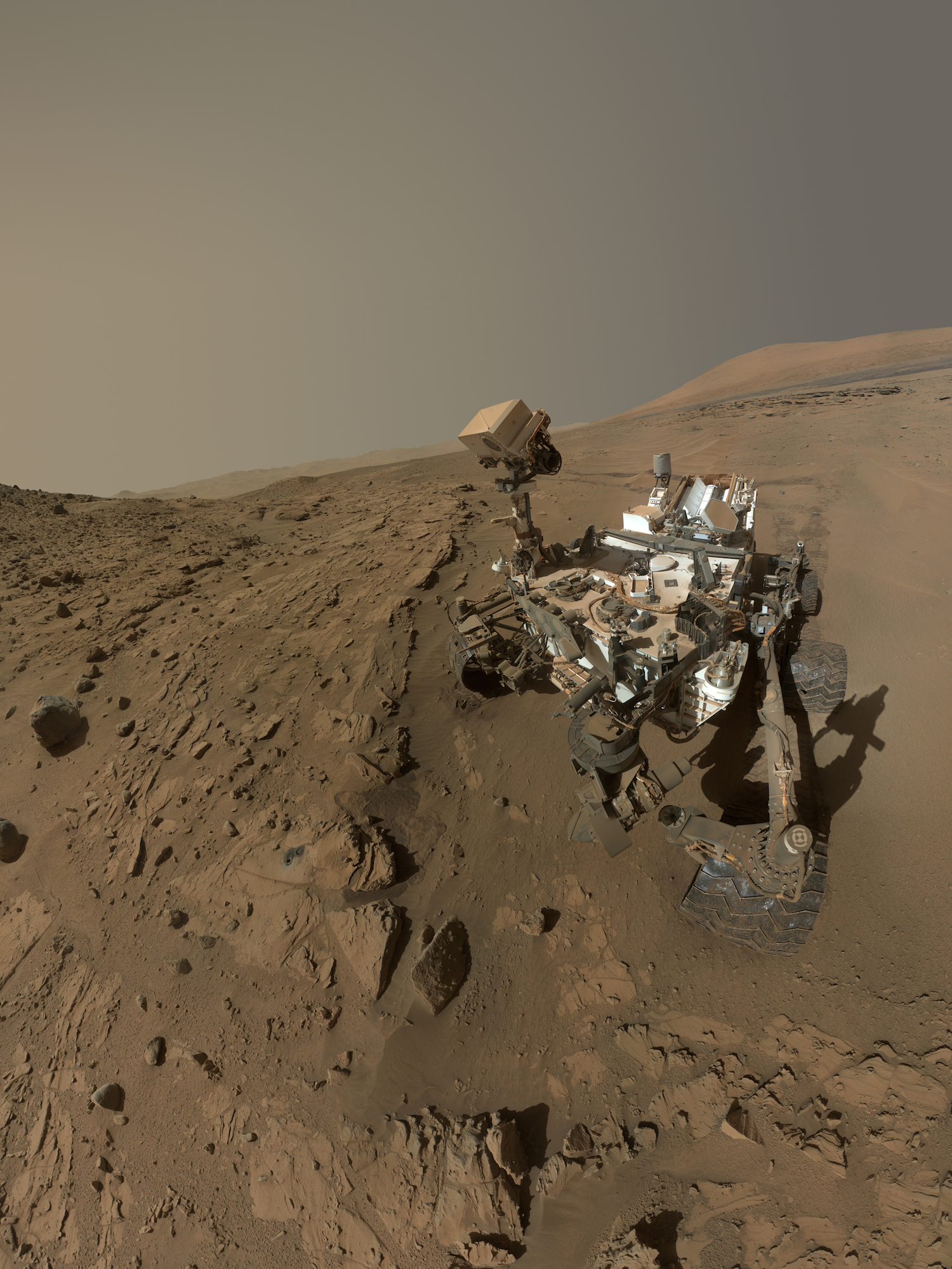
And what about Curiosity, the NASA Mars rover? You have probably heard of it, this is what the rover looks like:

Curiosity rover

Source: NASA

This is a “selfie”. It is real, it is not an artist reproduction, it is the real rover on Mars, those traces that you see are real traces on Mars soil (the image was built by collating together various pictures taken by different on-board cameras). The rover weighs 900 kg: this is the weight of a (modern) Fiat 500.  Think about it: humans have sent an autonomous, selfie-taking Fiat 500 to Marks, with a lot of scientific instruments on board.

As I said above, I don’t know what the world will look like in 3 or 4 or 10 years’ time and I don’t know what the job market will be like. But from Monday you have a unique opportunity: you can spend the next 3 years learning exciting new things and all the lecturers here are probably more excited than you about them. We will teach you some theory, programming languages, and even a bit of electronics, but you must be curious,  work independently and learn new things because you enjoy and because you like them. You will have lectures and labs, but we assume that you will spend a lot of time at home reading, trying to solve exercises and writing code. If you can do this, then you will be ready for whatever is waiting for us in the future, and you will have a lot of fun along the way.

If you are a new Computer Science student remember that you have a lot of ways to get involved and to contact us:


Calling Java from C++ on Mac OSX Mavericks with JNI and Java 8.

For a small research project I need to invoke Java from C++. More precisely, in the C++ code I need to create an object by calling a constructor and then invoke some methods. Surprisingly, I was not able to find a lot of information on-line. There are a number of tutorials to call C/C++ from Java, but not much for the other direction and very little for Java 8 on Mac. This is a very quick summary of what I’ve done, taken mainly from http://www.ibm.com/developerworks/java/tutorials/j-jni/j-jni.html and modified appropriately. Let’s start from a simple Java class, something like this:

package com.example.simple;
 
import java.util.List;
import java.util.ArrayList;
 
public class SimpleJNITest {
  List values;
 
  public SimpleJNITest() {
    values = new ArrayList();
  }
 
  public void addValue(String v) {
    values.add(v);
  }
 
  public int getSize() {
    return values.size();
  }
 
  public void printValues() {
    for (String v: values) {
      System.out.println("Value: " + v);
    }
}

This is nothing special: a simple Java class with a constructors and a few methods to add values to a list, get the list size, and print the values of the list to standard output. Save this file to SimpleJNITest.java in the directory com/example/simple (I assume you are working at the root of this directory). Now, let’s suppose you need to do the following from a C++ file:

  • Create a new object of type SimpleJNITest.
  • Add some values to this object.
  • Retrieve the number of values currently stored.
  • Invoke the printValues method to print values to screen.

The solution is the following (comments in the code. Make sure you read all the comments carefully before asking questions!).

/* Remember to include this */
#include <jni.h>
#include <cstring>
 
/* This is a simple main file to show how to call Java from C++ */
 
int main()
{
  /* The following is a list of objects provided by JNI.
     The names should be self-explanatory...
   */
  JavaVMOption options[1]; // A list of options to build a JVM from C++
  JNIEnv *env;
  JavaVM *jvm;
  JavaVMInitArgs vm_args; // Arguments for the JVM (see below)
 
  // This will be used to reference the Java class SimpleJNITest
  jclass cls;
 
  // This will be used to reference the constructor of the class
  jmethodID constructor;
 
  // This will be used to reference the object created by calling
  // the constructor of the class above:
  jobject simpleJNITestInstance;
 
  // You may need to change this. This is relative to the location
  // of the C++ executable
  options[0].optionString = "-Djava.class.path=.:./";
 
  // Setting the arguments to create a JVM...
  memset(&vm_args, 0, sizeof(vm_args));
  vm_args.version = JNI_VERSION_1_6;
  vm_args.nOptions = 1;
  vm_args.options = options;
 
 
  long status = JNI_CreateJavaVM(&jvm, (void**)&env, &vm_args);
 
  if (status != JNI_ERR) {
    // If there was no error, let's create a reference to the class.
    // Make sure that this is in the class path specified above in the
    // options array
    cls = env->FindClass("com/example/simple/SimpleJNITest");
 
    if(cls !=0) {
      printf("Class found \n");
      // As above, if there was no error...
 
      /* Let's build a reference to the constructor.
	 This is done using the GetMethodID of env.
	 This method takes 
	 (1) a reference to the class (cls)
	 (2) the name of the method. For a constructor, this is 
             <init>; for standard methods this would be the actual
             name of the method (see below).
	 (3) the signature of the method (its internal representation, to be precise). 
	     To get the signature the quickest way is to use javap. Just type:
             javap -s -p com/example/simple/SimpleJNITest.class
             And you will get the signatures of all the methods,
             including the constructor (check the "descriptor" field).
             In the case of the constructor, the signature is "()V", which
             means that the constructor does not take arguments and has no
             return value. See below for other examples.        
       */
      constructor = env->GetMethodID(cls, "<init>", "()V");
 
      if(constructor !=0 ) {
 
	printf("Constructor found \n");
	/* If there was no error, let's create an instance of the SimpleTestJNI by
	   calling its constructor
	*/
	jobject simpleJNITestInstance = env->NewObject(cls, constructor);
 
	if ( simpleJNITestInstance != 0 ) {
	  /* If there was no error, let's call some methods of the 
	     newly created instance
	  */
 
	  printf("Instance created \n");
 
	  // First of all, we create two Strings to be passed
	  // as argument to the addValue method.
	  jstring jstr1 = env->NewStringUTF("First string");
	  jstring jstr2 = env->NewStringUTF("Second string");
 
	  /* Then, we create a reference to the addValue method.
	     This is very similar to the reference to the constructor above.
	     As above, you can get the signature of the addValue method with javap.
	     In this case, the method takes a String as input and does not return
	     a value (V is for void)
	   */
 
	  jmethodID addValue = env->GetMethodID(cls, "addValue", "(Ljava/lang/String;)V");
 
	  /* Finally, let's call the method twice, with two different arguments.
	     (it would probably be a good idea to check for errors here... This is
	      left as a simple exercise to the student ;-).
	   */
	  env->CallObjectMethod(simpleJNITestInstance , addValue, jstr1);
	  env->CallObjectMethod(simpleJNITestInstance , addValue, jstr1);
 
	  /* Let's now call another Java method: printValues should print on screen
	     the content of the List of values in the object. The pattern is identical
	     to the one above, but no arguments are passed.
	  */
	  jmethodID printValues = env->GetMethodID(cls, "printValues", "()V");
	  env->CallObjectMethod(simpleJNITestInstance , printValues);
 
	  /* Finally, let's extract an int value from a method call. We need to
	     invoke CallIntMethod and we are going to use getSize of 
	     simpleJNITestInstance. Notice the signature: the 
	     method returns an int and it does not take arguments
	  */
	  jint listSize;
	  jmethodID getSize = env->GetMethodID(cls, "getSize", "()I");
	  listSize = env->CallIntMethod(simpleJNITestInstance , getSize);
 
	  printf("The size of the Java list is: %d\n", listSize);
 
        }
      }
      else {
	printf("I could not create constructor\n");
      }
    }
    jvm->DestroyJavaVM();
    printf("All done, bye bye!\n");
    return 0;
  }
  else
    return -1;
}

The code in itself is not too difficult. The main problem is getting the correct location of the various header files and libraries… To make the whole thing run, save the code above in a file (call it test.cpp) and do the following:

  • Compile the Java class: this is easy, just type
    javac com/example/simple/SimpleJNITest.java
  • Compile the C++ file: this is slightly more complicated because you need to specify various paths. The command on my machine (Mac OSX Mavericks, Java 1.8, gcc) is the following:
    g++  -o test \
     -I/Library/Java/JavaVirtualMachines/jdk1.8.0.jdk/Contents/Home/include \
     -I/Library/Java/JavaVirtualMachines/jdk1.8.0.jdk/Contents/Home/include/darwin \
     -L/Library/Java/JavaVirtualMachines/jdk1.8.0.jdk/Contents/Home/jre/lib/server/ \
     test.cpp \
     -ljvm
    

    You can remove the backslash at the end of each line if you write the command on a single line. The two -I directives tell where to find jni.h and jni_md.h; the -L (and -l) directive are used by the linker to find libjvm.dylib. If the compilation is successful, you should get an executable called test.

  • Before running test, you need to set LD_LIBRARY_PATH with the following instruction:
    export LD_LIBRARY_PATH=/Library/Java/JavaVirtualMachines/jdk1.8.0.jdk/Contents/Home/jre/lib/server/
  • From the same terminal where you have executed the command above, just type ./test.

Et voila, job done, if everything is OK you should see something like this:

$ ./test 
Class found 
Constructor found 
Instance created 
Value: First string
Value: First string
The size of the Java list is: 2
All done, bye bye!

Building an action camera using a Raspberry Pi and Java

20140625_205058I’m in charge of preparing some material for the new second year “Software Development” course here at Middlesex. As part of the new Java course I thought it would be a good idea to start exploring the Raspberry Pi GPIO (General Purpose I/O) pins with Java. These pins are very easy to use in Python, but with Java they require a bit more work (not much, don’t worry and keep reading).

Instead of just doing the usual exercises with traffic lights and digital inputs, I thought that it would be a nice idea to build a more “concrete” application. As a result, I decided to build an action camera that could be mounted on my bike helmet (by pure chance soon after after GoPro IPO 30% increase…). My plan is to have:

  1. A digital input switch (to set the camera on/off)
  2. A couple of LEDs to show the status of the application
  3. The standard Raspberry camera (the quality is excellent!)
  4. A USB WiFi dongle to make the Raspberry Pi an access point. Well, I’m not planning to use the Raspberry Pi as a router, I just would like it to set up a wireless network to which one could connect with a phone or a laptop to download the videos that are captured (TODO: I would like to implement a Racket-based web server to view the videos, delete them, etc.).

The final result (camera mounted on helmet) is shown above. This is a video made with the above set-up and with an appropriate “Twinkle twinkle Little Star” tune, given the time at which it was taken:

https://www.youtube.com/watch?v=aFguIT2qkTs

This is a picture of the wiring, see below for details:

JvPiwiring

OK, let’s start. I assume you have a working Raspbian image, a wireless dongle that works with hostapd (see http://raspberry-at-home.com/hotspot-wifi-access-point/), an input switch, a couple of LEDs and some experience with Linux and, more importantly, with Java. I’m using Java 8, but version 7 should work fine as well, see http://www.rpiblog.com/2014/03/installing-oracle-jdk-8-on-raspberry-pi.html for installation instructions. First of all you need to familiarise with the GPIO pins. This is a close-up picture of the GPIO pins (with some pins connected):

JvPi-wiring-closeup

Forget about the clarity, simplicity and engineering beauty of Arduino pins…

  • First of all, there are no numbers on the pins. Check carefully the picture above and you should see “P1″ on one of them: this is the only number you’ll get on the board.
  • There are three ways (that I know) to number the GPIO pins, and in most cases numbering is not sequential (see below).
  • The numbering has changed between Revision 1 and Revision 2
  • Revision 2 has an additional set of pins (but these are only accessible on the P5 header: turn the Raspberry Pi upside down and look for small holes: this is the P5 header). In the picture above you can see two holes to the right of R2: this is the beginning of the P5 header.

Keeping all this in mind, have a look at the table available at this link: http://wiringpi.com/wp-content/uploads/2013/03/gpio1.png. The two central columns (header) provide a progressive numbering. The columns “Name” contain the labels that are called “Board” in Python GPIO (for instance: the fourth pin on the left column from the top is called GPIO-zero-seven and 0V means “ground”). The column BCM GPIO contains another numbering (this numbering has changed between revision 1 and revision 2; for instance, BCM pin 21 in revision 1 is BCM pin 27 in revision 2). Finally, there is a “WiringPi Pin” numbering and this is the one that we are going to use with Java below. If you carefully check the picture above you’ll see, from left to right that:

  • There is one green wire connected to 0 V (ground) on header 9 and a red wire connected to WiringPi pin 1 (corresponding to GPIO 01): these will  control the red LED.
  • There is a red wire connected to WiringPi pin 2 (corresponding to GPIO 02) and a yellow one to 0 V (ground) on header 14: these will control the green LED.
  • There is a white wire connected to WiringPi pin 14 (header 23) and a purple one to 0 V (ground) on header 25. These will be connected to the on/off switch using a PULL-UP resistor (more on this later).

If you didn’t give up reading and you reached this point: congratulations, we are nearly there :-). It is now time to go back to Java and the first thing you need to do is to download Pi4J (http://pi4j.com/), a  library to “provide a bridge between the native libraries and Java for full access to the Raspberry Pi“. Get the 1.0 snapshot available at https://code.google.com/p/pi4j/downloads/list and extract it somewhere. Add this location to your Java classpath when you compile and run the code below.

You are now ready to write your first Java application to control GPIO pins. Let’s start with a very simple loop to turn a LED on and off (the famous Blink example in Arduino):

import com.pi4j.io.gpio.GpioController;
import com.pi4j.io.gpio.GpioFactory;
import com.pi4j.io.gpio.GpioPinDigitalInput;
import com.pi4j.io.gpio.GpioPinDigitalOutput;
import com.pi4j.io.gpio.Pin;
import com.pi4j.io.gpio.PinPullResistance;
import com.pi4j.io.gpio.RaspiPin;
 
//[...] add your methods here, then:
  GpioController gpio = GpioFactory.getInstance();
  GpioPinDigitalOutput redLED = gpio.provisionDigitalOutputPin(RaspiPin.GPIO_01);
  while (true) {
    // Add a try/catch block around the following:
    redLED.high();
    Thread.sleep(1000);
    redLED.low();
    Thread.sleep(1000);
  }

In the code above, you first need to import a number of packages; then, you set a GPIO controller and define an output pin attached to WiringPi pin 1 (with RaspiPin.GPIO_01). Then, the infinite loop keeps turning the LED on and off. Have a look at the documentation available online for additional examples: Pi4J is really well realised and there are plenty of examples available. For our action camera we are going to connect a red LED to GPIO_01 and a green LED to GPIO_02. These are configured as output pins. We then need an input pin and, more importantly, we need to start (or stop) recording when the state of this input pin changes. Pi4J provides a very convenient interface to detect pin changes. In the following example, we first define an implementation of this interface in the OnOffListener class:

import com.pi4j.io.gpio.event.GpioPinListenerDigital;
import com.pi4j.io.gpio.event.GpioPinDigitalStateChangeEvent;
 
public class OnOffStateListener implements GpioPinListenerDigital {
 
        @Override
	public void handleGpioPinDigitalStateChangeEvent(GpioPinDigitalStateChangeEvent event) {
            // Just print on screen for the moment
            System.out.println("State has changed");
        }
}

We then attach this listener to an input pin, as follows:

  GpioPinDigitalInput onOffSwitch = gpio.provisionDigitalInputPin(RaspiPin.GPIO_14, PinPullResistance.PULL_UP);	
  onOffSwitch.addListener(new OnOffStateListener());

Here we first define an input pin for WiringPi pin 14 and then we attach the listener defined above to this pin. Note that I define the input with a PULL_UP resistor (if you don’t know what this means, have a look at the Arduino documentation before moving to the next step!). If you try this code, you should get a message every time the input pin changes its state.

Building the full application is now a matter of gluing together these pieces and some instructions to turn the video recording on or off at each state change of the input pin. This is the full code for the main application:

package uk.ac.mdx.cs.jvpi;
 
import com.pi4j.io.gpio.GpioController;
import com.pi4j.io.gpio.GpioFactory;
import com.pi4j.io.gpio.GpioPinDigitalInput;
import com.pi4j.io.gpio.GpioPinDigitalOutput;
import com.pi4j.io.gpio.Pin;
import com.pi4j.io.gpio.PinPullResistance;
import com.pi4j.io.gpio.RaspiPin;
import com.pi4j.io.gpio.event.GpioPinDigitalStateChangeEvent;
import com.pi4j.io.gpio.event.GpioPinListenerDigital;
 
public class JvPi {
 
	// This is the controller.
	private GpioController gpio;
 
	// The current pin mapping
	private static final Pin redPin =  RaspiPin.GPIO_01;
	private static final Pin greenPin = RaspiPin.GPIO_02;
	private static final Pin switchPin = RaspiPin.GPIO_14;
 
	// The pins to which we attach LEDs
	private GpioPinDigitalOutput red,green;
 
	// this is going to be an input PULL_UP, see below.
	private GpioPinDigitalInput onOffSwitch;
 
	// set to true when capturing
	private boolean capturing;
 
	// Main method
	public JvPi() {
		this.gpio = GpioFactory.getInstance();
		this.red = gpio.provisionDigitalOutputPin(redPin);
		this.green = gpio.provisionDigitalOutputPin(greenPin);
		this.onOffSwitch = gpio.provisionDigitalInputPin(switchPin, PinPullResistance.PULL_UP);
 
		// The listener takes care of turning on and off the camera and the red LED	
		onOffSwitch.addListener(new OnOffStateListener(this));
	}
 
	public boolean isCapturing() {
		return this.capturing;
	}
 
	public void toggleCapture() {
		this.capturing = !this.capturing;
	}
 
	public GpioPinDigitalOutput getRed() {
		return this.red;
	}
 
	public GpioPinDigitalOutput getGreen() {
		return this.green;
	}
 
	public static void main(String[] args) {
		JvPi jvpi = new JvPi();
		jvpi.getGreen().high();
		System.out.println("System started");
		while (true) {
			try {
				Thread.sleep(1000);
			} catch (InterruptedException e) {
				// TODO Auto-generated catch block
				e.printStackTrace();
			}
		}
	}
 
}

The main method simply creates a new instance of JvPi that, in turn, attaches a listener to the input WiringPi pin 14. This is the code for the listener:

package uk.ac.mdx.cs.jvpi;
 
import java.io.IOException;
import java.text.SimpleDateFormat;
import java.util.Date;
 
import com.pi4j.io.gpio.event.GpioPinListenerDigital;
import com.pi4j.io.gpio.event.GpioPinDigitalStateChangeEvent;
 
public class OnOffStateListener implements GpioPinListenerDigital {
 
	private JvPi jvpi;
 
	private final String height = "720";
	private final String width = "960";
	private final String fps = "15";
	private final String destDir = "/home/pi/capture/";
 
	// Remember to add filename and extension!
	private final String startInstruction = "/usr/bin/raspivid -t 0 -h "+height+ " -w "+width+
			" -o "+destDir;
 
	private final String killInstruction = "killall raspivid";
 
	public OnOffStateListener(JvPi j) {
		this.jvpi = j;
	}
 
	@Override
	public void handleGpioPinDigitalStateChangeEvent(GpioPinDigitalStateChangeEvent event) {
        // display pin state on console
        if (this.jvpi.isCapturing()) {
          System.out.println("Killing raspivid");
          this.jvpi.getRed().low();
          killCapture();
        } else {
          System.out.println("Starting raspivid");
          this.jvpi.getRed().high();
          startCapture();
        }
        this.jvpi.toggleCapture();
 
    }
 
	private void killCapture() {
		executeCommand(this.killInstruction);
	}
 
	private void startCapture() {
		Date date = new Date() ;
		SimpleDateFormat dateFormat = new SimpleDateFormat("yyyy-MM-dd-HH-mm-ss");
		String filename = this.startInstruction + "vid-"+dateFormat.format(date) + ".h264";
		executeCommand(filename);
	}
 
	private void executeCommand(String cmd) {
		Runtime r = Runtime.getRuntime();
		try {
			r.exec(cmd);
		} catch (IOException e) {
			// TODO Auto-generated catch block
			e.printStackTrace();
		}
	}
 
 
}

As you can see, the code invokes raspivid if it was not capturing and it kills the raspivid process if it was running (TODO: improve error checking :-)! A number of default options, such as resolution and frame rate, can be configured here. The video is recorded to a file whose name is obtained from the current system date and time.

I have used a very basic box to store everything and I have attached the box to the helmet using electric tape: this is definitely not the ideal solution, but it is good enough for a proof of concept.

As usual, drop me an email (or leave a comment) if you have questions!

How to make a time lapse using a Raspberry Pi and Racket

racketlapseI have been using the Raspberry Pi camera for a few days and I have been really impressed by the quality of the image and video. As you know, I have also been playing a lot with Racket recently. Yesterday I thought that one could take a time lapse using Racket. In fact, I thought that one could build a “portable time lapse maker” as follows:

Put everything in your backpack, go on location, switch on the Raspberry Pi, attach your phone to the WiFi created by the Raspberry Pi, launch the job and you have an extremely portable, light and (hopefully) not-too-power-hungry time lapse maker. For instance, you could leave it on top of a mountain or next to the sea at night and go to pick it up the following day.

There was nothing on TV yesterday night, so I tried to see if it was possible to build a prototype. In the end, it turned out to be easier than I expected :-). I just had to play a bit with the parameters of raspistill but overall it took me:

  • 45 minutes to write takeTimeLapse.rkt from beginning to end.
  • 20 minutes to debug it and fix a few problems with parameters for raspistill.
  • 35 minutes to build the Illy waterproof box as described in the link above.
  • 10 minutes to build the cardboard version to be attached overhead (see picture above).
  • 25 minutes to write WebRacketLapse.rkt (with very little debugging, so it is probably not going to work very well… I have already noticed a bug: the thread variable is not set to null when the thread finishes, this needs to be fixed).

I have uploaded the code here: https://github.com/fraimondi/racketlapse. If you want to try it, just download it to your Raspberry Pi and launch racket WebRacketLapse.rkt.

This is the result of 1h30 mins of coding, so use with extreme caution! Contributors are welcome…

These are the results of some experiments:

  • Dawn in Temple Fortune: http://www.youtube.com/watch?v=BHUBwiwjZcs. I left the Illy box outside for the night using a 9000 mAH rechargable battery and I managed to have enough power to go for 8 hours and a half (the video is trimmed at the begin and at the end); the temperature was around 7 C. Considering that the WiFi USB dongle is probably using a lot of power, one can expect at least 10 hours of battery life if the dongle is disconnected. 8 hours of 1920×1080 images taken every 15 seconds took approx 2 Gb of disk space. I have and 8 Gb SD card, so plenty of space left.

I am happy with the results so far and. If anyone  has time to make this more user-friendly with a bespoke image for the Raspberry Pi and a better user interface in HTML, then I think it could have a number of applications. Drop me a line if you are interested.


The MIddlesex Robotic plaTfOrm: MIRTO

MIRTOMIRTO (the MIddlesex  Robotic plaTfOrm, also known as Myrtle) is an Arduino+Raspberry Pi platform currently used for teaching in the first year of the Computer Science degree at Middlesex University. It is developed as an open-source platform and the design and source code are available online (see links at the bottom of this post).

An overview of this first year has recently been given by Tony Clark at http://clarktony.blogspot.co.uk/2013/12/computer-science-approach-to-teaching.html, including  the motivations for our choice of Racket as the core programming language.

Myrtle is the main character of “block 3″ for first year Computer Science students (see previous link for an introduction to the idea of “blocks” and for an overview of our teaching and assessment strategy). The structure of Myrtle is the following:

1. A base layer incorporates Infra-Red sensors, bump sensors and a pair of HUB-ee wheels (see figure below):

sensors

 2. In the center, an Arduino Uno collects the data from the sensors and is connected to the wheels to drive them (see figure below): arduino-layer

3. The top layer for Computer Science students is a Raspberry Pi that is connected to the Arduino Uno board by means on a serial connection on the GPIO pins (a WiFi USB dongle is also visible in the figure below).

IMG_20140204_152433

This is a very flexible platform: Engineering students will employ mainly the Arduino layer (possibly two Arduino layers, one on top of the other) together with the Arduino IDE. Computer Science students will work mainly at the Raspberry Pi level, possibly extending the core platform with additional features (USB cameras, a fourth layer on top, etc.). More importantly, the platform offers a number of opportunities for teaching core Computer Science notions: from product of finite state machines to concurrency and synchronisation when reading the encoders, from networking at all levels (IP, TCP, applications) to data structures, functional programming, etc.

The software architecture of the platform for Computer Science students involves:

  1. A modified version of Firmata running on the Arduino Uno. This is an extension of Standard Firmata developed by Michael Margolis, the author of various books including the “Arduino Cookbook” and currently at Middlesex University.
  2. A Racket Firmata module extended with SysEx messages and other features used in Myrtle. This version works on Windows, Linux and Mac and detects the operating system automatically, together with the port to which the Arduino is attached.
  3. A Racket module (MIRTOlib.rkt) to interact with Myrtle using the Firmata library described above.

The following is an overview of block 3 for first year Computer Science students:

The students are initially exposed to the Arduino layer only to familiarize with MIRTOlib.rkt. In the figure below, Myrtle is provided without the Raspberry Pi layer and is connected directly to a PC or laptop using a USB cable. We employ this configuration to reason about interaction between components (wheels and sensors) using finite state machines, use cases, statecharts and sequence diagrams. We also have a local installation of MediaWiki for students so that they can document their progress using wiki pages they create. In the picture below, DrRacket is running on the PC/laptop and the Arduino layer of Myrtle is connected using a USB cable:

arduino-layer

Teaching then moves to networking, introducing IP addressing, TCP and network applications. The main result is an HTTP server built in Racket that can control an Arduino board using Firmata to turn on and off LEDs. The following is an example handout for the students addressing the HTTP server in Racket, starting from unquote + splicing, then moving to xexpr and finally to the actual HTTP server (click on the link to download the PDF):

A simple HTTP server in Racket (PDF)

In parallel, we start introducing some basic functions provided by MIRTOlib.rkt so that the students can move the wheels and read bump and IR sensors.

We then move to introducing a new architecture and a new operating system: Raspberry Pi  (ARM) and Linux. At this point we add the third layer to Myrtle and we “detach” the robot from the PC/laptop. We now access the robot over a wireless connection on the Raspberry Pi, where students upload Racket code and run it from the command line.

myrtlelab-top

The material now asks the students to reason about control . For instance, students are asked to print the IR sensors every 2 seconds and to move the wheels for 2 rotations, stopping immediately if one of the bump sensors is activated. In parallel, student learn how to read and post tweets using the Twitter API from Racket and they study encryption algorithms, authentication mechanisms and, in particular, OAuth 1.0 for Twitter.

Finally, students have a go at “control theory” with the problem of line following. This gives us a chance to talk a little bit about calculus (derivation and integration) to build a PID controller for the robot (click on the image for a video about this, available at http://www.youtube.com/watch?v=laafaTZ7mDU).

linefollowing

In the last two weeks the students will split into groups and will work on a project of their choice. Ideas include a web interface to drive the Myrtle wireless, control via majority voting using Twitter, advanced line following in various conditions, dancing robots, etc. I will provide additional details at the end of this block, together with the Racket code for line following and other examples: I don’t want to publish it now because students need to find it on their own!

So far, the results are very encouraging: we are nearly at the end of the course, with only 6 weeks left, and attendance is regularly above 90% (yes, this is 90% for all lab sessions in a cohort of approximately 120 students). Students are engaging with the material and it is common to see students remaining in the labs well after the end of the sessions.

Setting up this block has required a lot of preparation work by a number of people. Apart form all the academics and teaching assistants from the Computer Science department, we had enormous help from Michael Margolis, Puja Varsani and Nick Weldin.

In terms of practical issues:

  • So far, the robots seem to cope well with students using them, no major hardware failure reported in nearly 5 weeks of continuous usage. We have approximately 20 robots and we typically use 7 or 8 of them per session (each session is attended by approximately 20 students).
  • We have approximately 20 battery banks (9000 mAh), which are enough to go through a day of sessions. The batteries are recharged overnight.
  • Every week we provide a set of SD cards for the Raspberry Pi, setting up an environment with Racket and all the additional software required (voice recognition and image capture, for instance)

The source code for this platform is available at:

  • https://github.com/fraimondi/myrtle: Arduino code for the Arduino Uno layer (modified Firmata), MIRTOlib.rkt and some simple testing functions. Design files will be added very soon.
  • https://bitbucket.org/fraimondi/racket-firmata: platform-independent (in the sense that it seems to work well in Linux, Mac and Win) Firmata client for Racket. We have tested it with “standard” boards and it seems OK, even without Myrtle.
  • We also have an SD card image ready that includes Racket 5.3.6 pre-compiled. Send me an email if you want one of these.

Feel free to contact me if you need additional details!

An interesting problem with my socks

4160OFhBZiL._SX280_SY418_SH10_QL100_I have recently bought “7 Pairs of Cotton Rich Freshfeet Days of the Week Socks” from Marks & Spencer. Essentially, these are standard socks with the name of the day printed on them, from Monday to Sunday (i.e.: I have two socks marked “Monday”, two socks marked “Tuesday”, etc). They also come in different colours so that you don’t risk mixing socks from different days…

For the first week I tried to wear the correct socks for the correct day, but I immediately gave up and now I just pick a random pair from my drawer. After a few weeks I have noticed that the days in which I’m wearing the “correct” socks are a lot more than I expected (for instance, today is Monday and I have the correct pair, and last week I had the correct pair on two days of the week!). This looks like an interesting instance of the “Availability Heuristic” at work… What’s the probability of having the correct pair of socks?

Let’s simplify the problem: suppose that the week starts on Monday and all the 7 pairs of socks are available on that day. Suppose that every day you pick a random pair and you remove it from the available socks for the rest of the week (you obviously need to wash them…). What is the probability that at least once that during the week you have the right pair of socks for the correct day?

I’m going to show you 2 ways to compute this number (which is probably higher than you’d expect, and consistent with my surprise when I pick the correct pair of socks during the week):

1) The “I don’t have time to think of a solution / I hate Maths” way. Just write a simple Monte Carlo simulation and let the computer do the job. The idea is the following: start from the list (1 2 3 4 5 6 7), randomly shuffle the numbers around to obtain something like (3 4 7 2 1 6 5) (this is called a permutation and it represents the order in which you pick the socks: in this case, on Monday I pick the socks for Wednesday, on Tuesday those for Thursday, etc.), check if one of the numbers is in the right position (in this case yes: number 6 is in position 6, meaning that on Saturday I get the socks for Saturday), repeat the process N times and keep a counter of how many times the shuffled list has at least one number in the right position. At the end, just compute the ratio of this counter with respect to N. Let’s do it in Racket (obviously):

#lang racket
 
;; The number of days in the week
(define DOW 7)
 
;; The total number of iterations
(define N 1000000)
 
;; A simple function that takes a list and returns
;; True if one of the elements is in the right place
(define (oneIsOK myList)
  ;; The ormap builds first of all a new list by 
  ;; comparing the values of the list (1 2 ... DOW)
  ;; with the values of the input parameter myList, one
  ;; by one, thus producing a list of Boolean values.
  ;; It then compute the disjunction of this new list of 
  ;; Boolean values
  (ormap (lambda (value1 value2)
         (= value1 value2))
       (range 1 (+ 1 DOW))
       myList))
 
;; This is a simple for loop that repeats N random
;; shuffles of the list (1 2 ... DOW) and increments 
;; a counter when at least one element is in the right place.
(define (simulation)
  (define counter 0)
  (for ([i (range 0 N)])
    (cond ( (oneIsOK (shuffle (range 1 (+ 1 DOW))))
            (set! counter (+ 1 counter)))
          )
    )
  ;; at the end we just print the percentage
  (printf "The percentage is: ~a" (* 100.0 (/ counter N)))
  )

The code isn’t too difficult, check the comments above. The code runs 1 million shuffles and computes the results, which is 63% (more or less). Sixty-three percent! Wow, this means that it is more likely that in a week I have at least once the correct pair of socks! You can change the number of socks and see how this ratio changes. For instance, with 3 pairs of socks the probability is 66.6%: this is what you would expect, just check the 6 possible permutations of 3 elements.

2) The second method is the “I get a pen and a piece of paper“: let’s look again at the notion of permutation. What is needed here is to compute the number of permutations of (1 2 3 4 5 6 7) in which at least one of the elements “does not move” (more precisely, you should say “all the permutations with at least one fix-point”). One way to compute this number is to count the number of permutations in which all elements move (i.e., the number of permutations without fix-points): a permutation without fix-points is called a derangement. The notation !n is used to denote the number of derangements of n elements. Overall, we want to compute (n! – !n)/n!: this is the total number of permutations, minus the number of derangements, divided by the total number of permutations. To compute the number of derangements, observe that on Monday I can choose between 6 pairs of socks (i.e., all the ones not marked with Monday). Suppose that on Monday I get the Wednesday socks. There are now two options:

  1. I have a derangement in which on Wednesday I get the Monday socks. This leaves me with 5 pairs of socks to be arranged without fix-points, and there are !(n-2) ways for doing this.
  2. I have a derangement in which on Wednesday I do not get Monday’s socks, and there are !(n-1) ways for doing this.

Thus, there are (!(n-2)+!(n-1)) derangements in which on Monday I have the Wednesday socks. But Wednesday was just one of the possible (n-1) choices, so overall the number of derangements for n elements is:

!n = (n-1)(!(n-2) + !(n-1))

This is a nice recursive definition (just set !0=1 and !1=0), which we can compute with the following Racket code:

(define (der n)
  (cond ( (= n 0) 1)
        ( (= n 1) 0 )
        (else (* (- n 1) (+ (der (- n 1)) (der (- n 2)))))
        )
  )

With this function you can now compute the exact probability for 7 pairs of socks, which is 63.21%.

EXERCISE: compute the average number of days per week in which I wear the correct pair of socks. HINT: the solution is 1, and this is equivalent to the claim that “the average number of fix-points in a random permutation is 1“, irrespective of the size of the list…

The classic Simon memory game in Racket + Arduino

OriginalSimon

(Source: Wikipedia)

The Simon memory game is one of the first electronic games I remember from my childhood, together with late 70′s Atari consoles and early 80′s  Game & Watch Nintendo handheld (Donkey Kong was my favourite).

The game is very simple: there are four coloured buttons that correspond to four different tones. The game presents a sequence of colours and the player has to repeat the sequence. If the player is successful, a further colour is added, otherwise a horrible 42 Hz saw-shaped sound is emitted; check this commercial http://www.youtube.com/watch?v=yF0ZUXclW8Y

It is not difficult to implement the game in Racket using an Arduino UNO board with four LEDs and four digital buttons, connected using Firmata.

IMG_20131207_074841I have connected the LEDs to PINs 8, 9, 10 and 11; I have connected the buttons to PINs 2, 3, 4 and 5. The figure on the left shows the spaghetti-like circuit. If you want to see what happens when you run the code, have a look at this link of my daughter playing with it: http://youtu.be/tk69MUwQs5A (in Italian with some subtitles…)

This game is very interesting for teaching purposes: it is easy enough to be covered in a session, but it also contains some issues that are not so simple, such as distinguishing between a state in which the code displays the sequence from a state in which the player is entering the sequence. The sequence is not fixed and it needs to be reset when the player makes a mistake. One exercise I will do in class is to ask the students to write down all the possible states and the possible transitions.

Let’s now  have a look at a possible Racket code for this. I assume you have Firmata installed on your Arduino UNO and you also know how to connect it to Racket using Firmata to read a button. If this is not the case, it is probably better if you have a look at this other link before proceeding: http://www.youtube.com/watch?v=7Zzh7qrQph4. I start with

The following is the description of a possible Racket implementation of the game; it is available with sound files and firmata at this link: http://www.rmnd.net/racket/simon. The implementation could be improved in a number of ways, see at the bottom of this post for a list of tasks for students. I start by including the appropriate Firmata module and by declaring the PINs to which the LEDs and the push buttons are connected to. I then define two lists that I use in other places in the code to initialise the PINs and to do boot sequences.

;; change as appropriate for your OS
(require "firmata-mac.rkt")
 
(define yellow 8)
(define green 9)
(define red 10)
(define blue 11)
 
(define in-yellow 2)
(define in-green 3)
(define in-red 4)
(define in-blue 5)
 
(define colours (list yellow green red blue))
(define in-colours (list in-yellow in-green in-red in-blue))

To keep track of the various buttons being pressed, I extend the code at http://www.youtube.com/watch?v=7Zzh7qrQph4 defining four sets of states for the buttons (all initially UP):

(define curStateYellow "UP")
(define previousStateYellow "UP")
 
(define curStateGreen "UP")
(define previousStateGreen "UP")
 
(define curStateRed "UP")
(define previousStateRed "UP")
 
(define curStateBlue "UP")
(define previousStateBlue "UP")

I then declare a list that I use to store the sequence of states to be guessed with
(define seq '()). The key idea of the game is to use “states” to keep track of what the code should do. We start from a state “gameOver”, declaring it with (define state "gameOver").
I then declare a few support functions, see comments in the code below:

;; Show a sequence of colours: switch on a PIN, play the
;; corresponding sound with play-index (see below), clear
;; the PIN, wait 0.2 seconds and then call itself recursively until
;; there is something to show.
(define (showSeq s)
  (cond ( (&gt; (length s) 0)
          (set-arduino-pin! (first s))
          (play-index (first s))
          (clear-arduino-pin! (first s))
          (sleep 0.2)
          (showSeq (rest s))
          )
        )
  ) ;; end of showSeq
 
;; play a note using its position in the list (yellow - green - red - blue)
;; (see below the definition of play)
(define (play-index i)
  (cond ( (= i yellow) (play "yellow"))
        ( (= i green) (play "green"))
        ( (= i red) (play "red"))
        ( (= i blue) (play "blue"))
        )
)
 
;; play a sound with afplay (works on a mac)
;; in Linux, you can use aplay.
;; It just calls a command-line using system
(define (play note)
  (system (string-append "afplay " note ".wav &amp;"))
  )
 
;; This is used to set-up the mode of the various PINs. I do
;; so using the high-order function map, together with a lambda
;; function
(define (setup)
  (map (λ (i) (set-pin-mode! i OUTPUT_MODE)) colours)
  (report-digital-port! 0 1)
  (map (λ (i) (set-pin-mode! i INPUT_MODE)) in-colours)
)

The core of the code is the function mainLoop that loops through the following sequence of states (code below, after this list):

  • gameOver: this is either the initial state or the state following a wrong choice by the player. In this state we clear the sequence of colours and we generate a new random initial colour. After gameOver the code shows (and play with sounds) the sequence to the player.
  • After showing the sequence, the code moves to state playing. In this state we go through a new loop, see playingLoop below.
  • The code exits playingLoop either when the player guesses all the sequence correctly or when the player makes a mistake. In the former case the code enters a state called “correctSequence”; in the latter it enters a state called “wrongChoice”.
  • In state “correctSequence” the code adds a new colour to seq and then shows the sequence. It then goes back to state “playing”.
  • In state “wrongChoice” the code moves to gameOver and repeats the loop.

This is the full code for the function:

(define (mainLoop)
 
  (cond ( (equal? state "gameOver")
          (printf "DEBUG: Current state is gameOver\n")
          ;; If we are in game over, we clear the sequence, we add
          ;; a random value and we set state to "playing"
          (set! seq '())          
          (set! seq (append seq (list (list-ref colours (random (length colours))))))
          (sleep 0.5)
          (set! state "showSequence")
          )
 
        ( (equal? state "showSequence")
          (printf "DEBUG: Current state is showSequence\n")
          ;; We show the sequence and then we enter playing
          (sleep 0.3)
          (set! state "playing")
          (showSeq seq)
          )
 
        ( (equal? state "playing")
          (printf "DEBUG: Current state is playing\n")
            ;; We enter the main playing loop, see below (player does things)
           (playingLoop seq)
        )
 
        ( (equal? state "wrongChoice")
          ;; The player has made a wrong choice:
          ;; we enter game over state
          (sleep 0.5)
          (set! state "gameOver")
          )
 
        ( (equal? state "correctSequence")
          (set! seq (append seq (list (list-ref colours (random (length colours))))))
          (sleep 0.5)
          (showSeq seq)
          (set! state "playing"))
  )
  (mainLoop) ;; call recursively
) ;; end of mainLoop

The player interacts with the push buttons in the playingLoop function. The function takes in input a sequence (of colours) and expects that the player presses the first colour in the list. If this is the case, it calls itself recursively on the tail of the sequence of colours. Otherwise, it sets state to “wrongChoice” and plays the horrible 42 Hz sound. The code is a simple extension of the code described in FIXME to 4 buttons. The full code is the following:

;; The playing loop: the player has to guess the sequence s, we call ourselves
;; recursively on s.
(define (playingLoop s)
 
  ;; to keep track of a correct choice, used to loop at the end
  (define correct "")
 
  (cond ( (= (length s) 0)
          ;; if the list is empty, we guessed all the colours correctly!
          (set! state "correctSequence")
          (printf "DEBUG: well done, the sequence is correct!\n")
          )
        (else 
         ;; There are more colours to be guessed, we keep looping here
         ;; recording what is being pressed
         (cond ( (is-arduino-pin-set? in-yellow) (set! curStateYellow "DOWN"))
               (else (set! curStateYellow "UP")))
         (cond ( (is-arduino-pin-set? in-green) (set! curStateGreen "DOWN"))
               (else (set! curStateGreen "UP")))
         (cond ( (is-arduino-pin-set? in-red) (set! curStateRed "DOWN"))
               (else (set! curStateRed "UP")))
         (cond ( (is-arduino-pin-set? in-blue) (set! curStateBlue "DOWN"))
               (else (set! curStateBlue "UP")))
 
         ;; switch on the lights and check if it is correct when we release
 
         ;; Blue
         (cond ( (and (equal? curStateBlue "DOWN") (equal? previousStateBlue "UP")) 
                 (printf "DEBUG: blue pressed\n")
                 (set-arduino-pin! blue)
                 (play "blue")
                 ))
         (cond ( (and (equal? curStateBlue "UP") (equal? previousStateBlue "DOWN")) 
                 (printf "DEBUG: blue released\n")
                 (clear-arduino-pin! blue)
                 (cond ( (= (first s) blue) 
                         ;; the player chose the right colour
                         (set! correct "T")
                         )
                       (else (set! correct "F"))
                       )                       
                 )
         ) ;; end of blue button released
        ;; You need to repeat the code above for the three remaining colours,
        ;; see source code available on-line at the link below.
         ;; Setting the previous states
         (set! previousStateBlue curStateBlue)
         (set! previousStateRed curStateRed)
         (set! previousStateGreen curStateGreen)
         (set! previousStateYellow curStateYellow)
         (cond ( (equal? correct "T") 
                 (playingLoop (rest s)))
               ( (equal? correct "F") 
                 (set! state "wrongChoice")
                 (printf "DEBUG: ops, wrong choice!\n")
                 (play "wrong"))
               (else (playingLoop s))
         )
         ) ;; end else (sequence not empty)
        ) ;; end cond
)  ;; end playingLoop

This completes more or less the code. There are other minor things that could be added, see the code available online at http://www.rmnd.net/racket/simon. You can launch the code by setting the appropriate port for Firmata. I have run this code both on a Mac laptop and on a Raspberry Pi and it works fine. I have not tried Windows… let me know if it works for you.

Possible tasks for students:

  • A lot of code is repeated, for instance in playingLoop. Improve it by reducing the amount of duplicated code.
  • Calling OS instructions using (system ) causes the code to stop while the command is being executed because it is a synchronous call. Implement system calls using (process ). You need to manage timing for this is a different way…
  • In the original Simon game, the timing between different colours / sounds in the presentation state as you progress with levels. Modify the code to take this into account.
  • Introduce a winning state, e.g., if the player can guess a sequence of 15 colours.
  • Save best scores, or publish them on-line (Twitter, Facebook, Google+)

Speech recognition on Raspberry Pi with Sphinx, Racket and Arduino

IMG_20131112_112628 copyIn this post I put together a number of things to control two LED from a Raspberry Pi with voice recognition (via Sphinx), Firmata and Arduino. Before you start, you may want to have a look at this other post on how to connect a Raspberry Pi and an Arduino board using Firmata and Racket: http://jura.mdx.ac.uk/mdxracket/.

First of all, we need to install PocketSphinx on Raspberry Pi to do speech recognition. I am using a standard USB camera with microphone (supported by Raspberry Pi) and I’m following the instructions available here: https://sites.google.com/site/observing/Home/speech-recognition-with-the-raspberry-pi. In essence, this is what I’ve done (as root on the Raspberry Pi), please see the link above for additional details:

apt-get install rpi-update
apt-get install git-core
rpi-update

-> Connect your USB microphone (or camera+mic) and
-> reboot the RPi at this point

vi /etc/modprobe.d/alsa-base.conf 

# change as follows:
# Comment this line
# options snd-usb-audio index=-2
# and add the following:
options snd-usb-audio index=0

-> close the file and reload alsa:

alsa force-reload

wget http://sourceforge.net/projects/cmusphinx/files/sphinxbase/\
0.8/sphinxbase-0.8.tar.gz/download
mv download sphinxbase-0.8.tar.gz
wget http://sourceforge.net/projects/cmusphinx/files/\
pocketsphinx/0.8/pocketsphinx-0.8.tar.gz/download
mv download pocketsphinx-0.8.tar.gz
tar -xzvf sphinxbase-0.8.tar.gz
tar -xzvf pocketsphinx-0.8.tar.gz

apt-get install bison
apt-get install libasound2-dev

cd sphinxbase-0.8
./configure --enable-fixed
make
make install

cd ../pocketsphinx-0.8/
./configure
make
sudo make install

Et voila’, you are now ready to test your PocketSphinx installation. Go to pocketsphinx-0.8/src/programs and run:

./pocketsphinx_continuous

If you are lucky, you should get some text back… I don’t have space here (and time) to go into the details of (pocket)sphinx. Try some simple words and see if they are recognised. I ended up building a very very simple language model using the on-line tool at this link: http://www.speech.cs.cmu.edu/tools/lmtool-new.html. I use just “green”, “red” and “off” and they seem to work fine in spite of my Italian accent.

In the next step we need to connect the output of PocketSphinx with Racket. I do this in a very primitive way: I modify the source code of pocketsphinx_continous to output just the word that is recognised. This is very simple: just modify continous.c under pocketsphinx-0.8/src/programs, comment all the printf statement and output just the recognised word (drop me an email if you don’t know how to do this). I append a “RACKET: ” string at the beginning of the printed string to make sure that this is something I have generated. You can then run pocketsphinx and redirect the output to a file with something like:

./pocketsphinx_continuous -lm /home/pi/sphinx/simple/4867.lm \
   -dict /home/pi/sphinx/simple/4867.dic > /tmp/capture.txt

(notice that I’m using the language model + dictionary generated on-line)

Time now to go back to Racket. I assume you know how to connect a Raspberry Pi with an Arduino board and talk to it in Racket using Firmata (if this is not the case, please have a look at the instructions available at http://jura.mdx.ac.uk/mdxracket/index.php/Raspberry_Pi,_Arduino_and_Firmata). In the following Racket file I simply read the file /tmp/capture.txt and send instructions to the board according to the instructions received. If a command is not recognised, I print a message on screen. The code for this is the following:

#lang racket
(require "firmata.rkt")
 
(define green 12)
(define red 13)
 
(define in (open-input-file "/tmp/capture.txt"))
 
(define (process-input str)
  (printf "processing input ~a\n" str)
  (set! str (substring str 8))
  (cond ( (string=? (string-upcase str) "RED")
          (printf "I'm setting red\n")
          (set-arduino-pin! red)
          )
        ( (string=? (string-upcase str) "GREEN")
          (printf "I'm setting green\n")
          (set-arduino-pin! green)
          )
        ( (string=? (string-upcase str) "OFF")
          (printf "I'm clearing the PINs\n")
          (clear-arduino-pin! red)
          (clear-arduino-pin! green)
          )
        (else
         (printf "Sorry I cannot understand: ~a\n" str)
         (flush-output)
         )
  )
  )
 
(define (read-loop)
  (define str (read-line in))
  (unless (eof-object? str)
               (process-input str)
    )
  (read-loop))
 
(define (start-everything)
  (open-firmata "/dev/ttyACM0")
  (set-pin-mode! green OUTPUT_MODE)
  (set-pin-mode! red OUTPUT_MODE)
  (read-loop)
  )
 
(start-everything)

Job done. Now check that:

  • The modified version of pocketsphinx_continuous is running and redirecting the output to /tmp/capture.txt
  • Launch the file above with something like racket sphinx-arduino.rkt
  • Check that your Arduino board is connected and wired up appropriately

and you should get something like this:

http://youtu.be/XGYNRHWY4Ag

Future work:

  • I don’t think there is a need to write to a file… maybe pocketsphinx can redirect to a port and Racket can listen to it?
  • Improve the language model for a domain of your choice
  • Add a couple of speakers to the Raspberry Pi so that Racket can tell you what it is doing, if something has not been recognised, etc.

Racket and TinyOS via USB

IMG_20131029_151628Communication between a PC and a TinyOS mote is normally achieved using Java. But what if you want to use Racket?

Here I give a very simple overview of how packets from a TinyOS mote connected via USB to a Linux or Mac machine can be read using Racket (I have not tried Win). An advantage of this approach is that it does not require the installation of TinyOS, which could be quite cumbersome… However, it may be a good idea to have a working installation of TinyOS on your machine so that you can modify the code on the motes. It would be beneficial to have at least a bit of familiarity with nesC (no need to be able to write code, just to understand a little bit what is going on).

As an example, I start from a simple application that broadcasts temperature and humidity. The application can be installed on various motes (just 2 in my configuration) and then a base station collects all the readings. In my case the base station is connected to the PC using a USB port. In my configuration I have a Ubuntu virtual machine running on a Mac where I have configured the TinyOS environment and Racket is running in this virtual machine. The same code runs directly on Mac. We are only interested in the structure of the message being broadcasted. This is a small variation of the standard examples that can normally be found in a .h header file; in my example the header file contains the following:

1
2
3
4
5
typedef nx_struct BlinkToRadioMsg {
  nx_uint16_t nodeid;
  nx_uint16_t humidity;
  nx_uint16_t temperature;
} BlinkToRadioMsg;

This says that each message contains 2 bytes (16 bits) for nodeid, 2 bytes for humidity and 2 bytes for the temperature, for a total of 6 bytes. Messages are transmitted in TinyOS packets over the wire, and these packets have a special format. See Section 3.6 of the document available at http://www.tinyos.net/tinyos-2.x/doc/html/tep113.html if you want more information. In summary, a packet looks like this:

7e 45 00 ff ff 00 01 06 22 06 00 01 04 5c 18 69 37 6b 7e

where the sequence 7e is a reserved sequence to denote the start and the end of a packet. The actual payload (i.e., the 6 bytes we want to receive) in our case is the sequence “00 01 04 5c 18 69″, where “00 01″ is nodeid, “04 5c” are the two bytes for humidity and “18 69″ are the two bytes for temperature. The rest of the packet includes a CRC check, protocol ID, etc. See link above if you are interested in the details.

To read these packets I modify a little bit the code that is used in firmata.rkt to communicate with an Arduino board using firmata. The idea is simple: I create an input file attached to the USB port and I keep reading bytes. When I recognise a packet, I parse it an print the values of ID, humidity and temperature on screen. Let’s start by creating the input file:


1
2
3
4
5
6
7
8
9
10
11
12
13
14
15
16
17
18
;; This is the input file to be defined below
(define in null)
 
;; This is used to open the connection and to launch the reading loop
;; You typically launch it with (open-port "/dev/ttyUSB0)"
;; (check the port name with the command-line instruction motelist)
(define (open-port port-name)
  (printf "Racket-TinyOS starting... please wait\n")
 
  ;; This is used to associate the port to the file
  (set! in (open-input-file port-name #:mode 'binary))
  (if (system (string-append "stty -F " port-name " 115200 cs8 cread clocal"))
    (begin
     (read-loop) ;; see below for the definition of this
    )
    (error "Could not connect to " port-name)
  )
)

The (read-loop) simply reads one byte at a time and calls itself:

1
2
3
4
(define (read-loop)
  (process-input (read-byte in))
  (read-loop)
)

The function (process-input) is where the packet is built:

1
2
3
4
5
6
7
8
9
10
11
12
13
14
15
16
17
18
19
20
21
22
23
24
25
26
27
28
29
30
;; This is where we store the packet
(define packet null)
 
;; These are used to define the end-of-packet and start-of-packet sequences
(define sop #x7e) ;; start of packet
(define eop #x7e) ;; end of packet
 
;; These are used to record the fact that an end-of-packet 
;; (or start-of-packet) have been received
(define eop-rec 0) ;; end-of-packet received
(define sop-rec 0) ;; start-of-packet received
 
(define (process-input data)
  ;; First of all we add the byte to the packet
  (set! packet (cons data packet))
  (cond ( (and (= eop-rec 0) (= data eop))
          ;; If it is an end-of-packet sequence, we record it
          (set! eop-rec 1)
          )
        ( (and (= eop-rec 1) (= data sop))
          ;; If we find a start of packet after an end-of-packet we parse
          ;; the packet (we have to reverse it, because it was built in
          ;; the opposite order)
          (parse-packet (reverse packet))
          ;; and then we start again and we empty the packet.
          (set! eop-rec 0)
          (set! packet null)
          )
        )
)

Up to this point the code is re-usable for any packet content. In the function (parse-packet), instead, we have to process the bytes according to the message format defined in the header file (see above). This function is defined as follows:

1
2
3
4
5
6
7
8
9
10
11
12
13
14
15
16
17
18
19
20
21
22
(define (parse-packet packet) 
 
  ;; Very easy: ID is at position 10 and 11
  ;;            Humidity position 12 and 13
  ;;            Temperature position 14 and 15
 
  ;; These functions get the two bytes into the actual ID,
  ;; humidity and temperature. 
  ;; for the actual formula
  (define id (+ (* (list-ref packet 10) 256) (list-ref packet 11)))
  (define rh (+ (* (list-ref packet 12) 256) (list-ref packet 13)))
  (define temp (+ (* (list-ref packet 14) 256) (list-ref packet 15)))  
 
  ;; We then convert RH and temp according to datasheet for sensirion sht11
  (set! rh (+ (* rh 0.0367) -2.0468 (- (* 0.00000159 rh rh))))
  (set! temp (+ (* temp 0.01) -39.7))
 
  ;; Omissis: print the actual date. See link below for full code.
 
  (printf "~a ~a ~a\n" id rh temp)
  (flush-output)
  )

The final result of this code is the following output

2013/10/29 17:04:55 1 61.36022401 10.379999999999995
2013/10/29 17:05:02 2 35.30190249 23.799999999999997

Where the first number after the time is the node id, followed by the relative humidity, followed by the temperature. I have redirected this output to a file called office-all.txt for one hour, placing one sensor inside my office (with sensor id 2) and one sensor outside the office (sensor id 1). At the end of the hour I split this file with the command-line instruction

grep " 1 " office-all.txt > office-out.txt
grep " 2 " office-all.txt > office-out.txt

Then, I plot the temperature with the following gnuplot script:

set timefmt "%Y/%m/%d %H:%M:%S"
set xdata time
set terminal png font "/Library/Fonts/Arial.ttf" 28 size 1600,1200
set output 'office-temp.png'
plot "office-out.txt" using 1:5 title "Outdoor", "office-in.txt" using 1:5 title "Indoor"

This is the final result:

office-tempNotice how the indoor temperature remains constant (in green), while the outdoor temperature drops in 10 minutes when the sensor adjusts to the outdoor temperature, and it keeps decreasing as the sun sets. A very similar script for relative humidity produces this graph:

office-rh

(notice how the relative humidity outside increases as the temperature decreases).

You can download the full Racket code by clicking here.

*** NOTICE!!! *** The parse-packet function is broken: it should take into account the escape sequences before parsing! I leave this to you to fix :-).

A very simple introduction to Fluxus and Fluxa

Screen Shot 2013-10-23 at 13.02.45This is a very simple write-up of my experiments with Fluxus and Fluxa to generate sounds (I don’t call it music…). It is intended for students who know a bit of Racket but have no experience at all with Fluxus and Fluxa. The results are just an example of what can be done, I hope someone will start from these to produce something better.

Back to Fluxus and Fluxa: if you have managed to install it (see my other post on How to Install Fluxus on Mac), make sure that you have Jack running and that you launch fluxa from the command line. Then, launch Fluxus and you can start with the experiments.
First, you need the following line:

(require fluxus-018/fluxa)

Then, you can start playing sounds immediately. For instance, try this:

(play-now (mul (sine 440) (adsr 1 1 1 1)))

The instruction above does the following: it generates a sinusoidal wave of frequency 440 Hz with the instruction (sine 440), and then it multiplies this signal with an adsr envelope with attack, drop, sustain and release all set to 1. If you are like me and don’t have an idea of what an adsr envelope is, please have a look at this simple introduction to synthesizers: http://beausievers.com/synth/synthbasics/

There are different wave forms available in Fluxa: in addition to sine, there is squ (square), tri (triangle) and saw. There are also white and pink noise generators.
It doesn’t stop here: you can use a lot of filters, including various moog filters. Have a look at this page if you are interested: http://www.pawfal.org/fluxus/docs/0.17/en/fluxa.html.

All these ingredients are typically put together in a loop to play music. In fluxa, you use the following construct:

(seq
  (lambda (time clock)
    (when (zmod clock 2)
      (play time (mul (sine (mul 100 (pow (adsr 0 0.1 0.8 1) 6)))
       (adsr 0 0.5 0.4 5))))
  0.5)
)

This is a loop that is repeated every 0.5 second. The lambda function has two parameters: the absolute time (in seconds, since the start of Fluxus) and an integer counter called clock.
The function (zmod clock 2) is true when the value of the clock is a multiple of two, i.e., every other iteration. As each iteration lasts 0.5 seconds, the play instruction is repeated every second; notice that here we use play and not play-now. Play takes and additional time parameter to specify when it should be executed. The magic combination of mutlipliers and adsr envelopes above generates a heart beat (I have copied this from one of the example available in the source code).

You can use fluxa to learn everything you need to know (and a bit more) about modulo functions, synchronization, and reasoning about time. These are some of the examples I have created:

  • Close Encounters of the Third Kind (CETK): just five notes repeated with increasing BPM. You can download cetk.scm here.
  • The SOB beat: instead of using the seq mechanism of fluxa, I use every-frame and plot a graph together with a beat for each SOB, more or less (a SOB is a “Student Observable Behaviour”, a new mechanism of assessment that we use for our undergraduate students of Computer Science; each student is supposed to demonstrate a certain number of SOBs during the year, and we record these using a dedicated tool from which I have exported the observations so far). The graph is equivalent to the one visible from our SOB admin dashboard, with students on the x axis and number of observed SOBs on the y axis. For each student I play a number of beats equal to the number of SOBs. This result in an increasing heartbeat. You can download SOB-beat.scm here and you can also watch a screen capture on Youtube at http://www.youtube.com/watch?v=WWMEfdbk4Kw (you may need to increase your volume)
  • The SOB melody: this is very similar to the previous one, but instead of playing a beat I play a note from a scale. For each student I change the scale in a random way (only 2 scales for the moment). You can download SOB-melody.scm here and you can watch the corresponding screen capture (with some live comments) here: http://youtu.be/1dO1CSgfpBc
  • Finally, back to the seq mechanism and a few operations with modulo: I take the list of SOB id in the order in which they are observed and I play them back in a random scale (selected at the beginning). You can download The delicate sound of sobs here.

Feel free to play around with these files and let me know if you obtain something better!