Category Archives: Raspberry Pi

Controlling an Arduino board via USB with the ASIP protocol

mirto
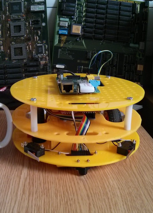
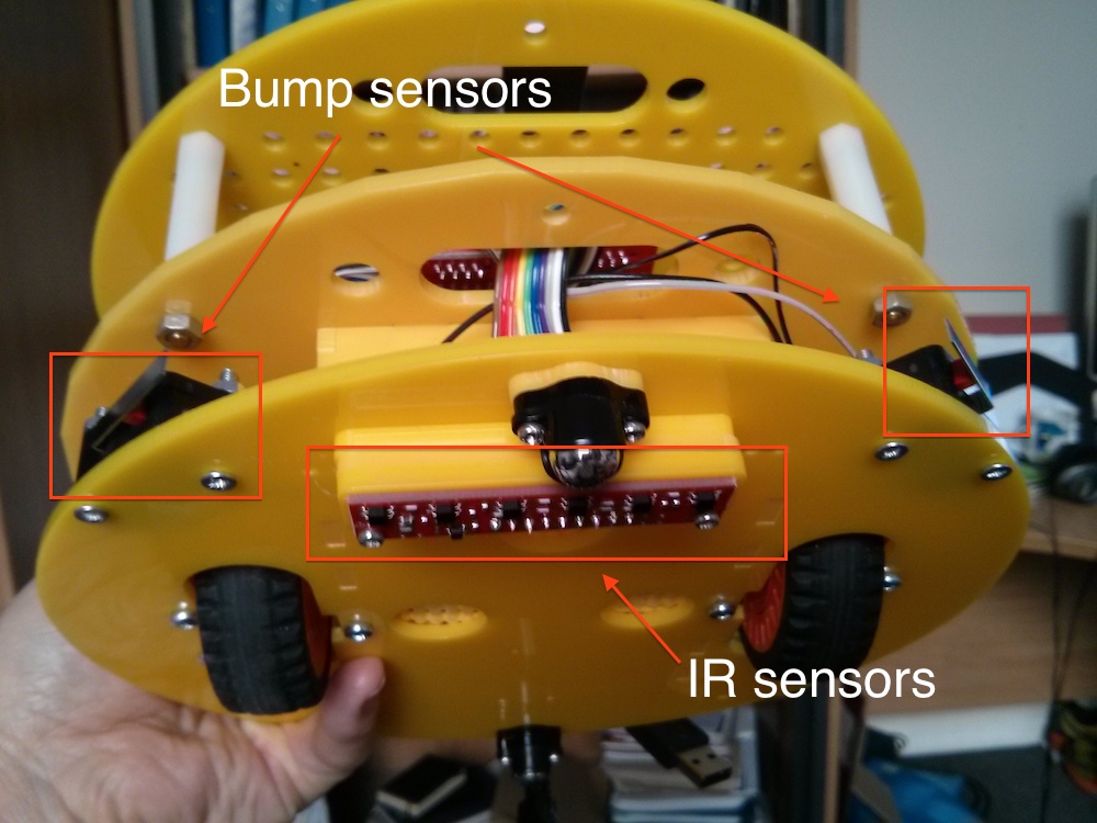
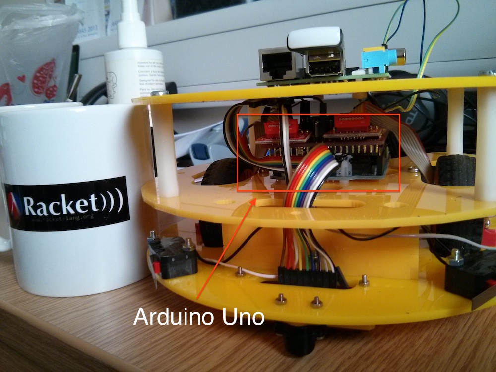
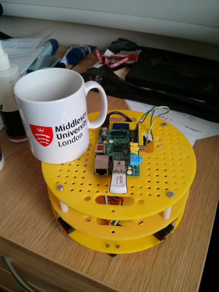
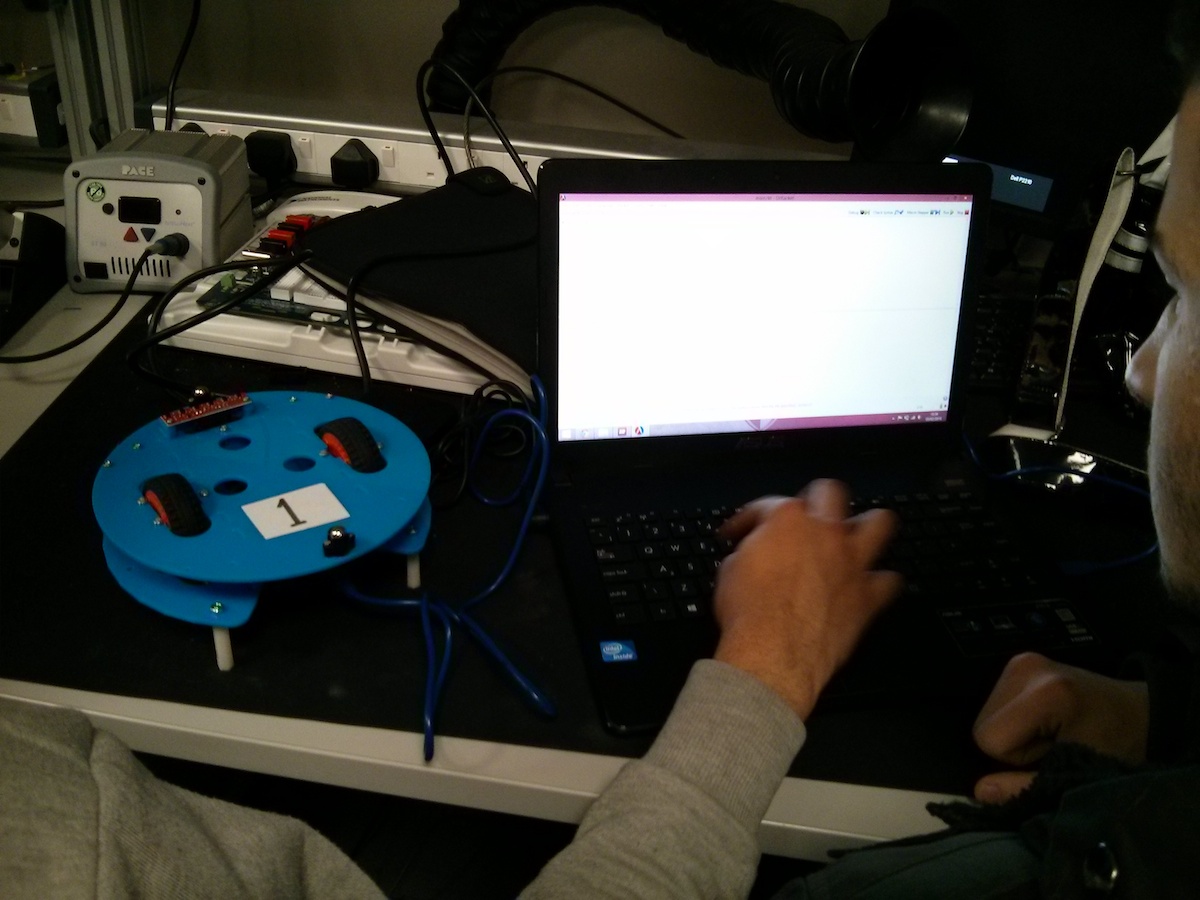
Last year we built the Middlesex Robotic Platform (MIRTO) using a Raspberry Pi and an Arduino Uno board. In our configuration the Arduino board is essentially a “slave” of the Raspberry Pi. A pair of HUB-ee wheel, infra-red sensors and bumper sensors are attached to the Arduino board, but all the “logic” is on the Raspberry Pi. It is the Raspberry Pi that sends the instructions to read the IR values and to set the speed of the wheels. In our configuration, the Arduino board is attached to the Raspberry Pi using a serial connection (GPIO pins on the Raspberry Pi and pin 0 and 1 on the Arduino). In MIRTO we installed Firmata on the Arduino board and we extended Firmata clients available on the Raspberry Pi. More precisely, we had to extend Firmata with specific messages for wheels (both directions: to set the speed and to read quadrature encoders) and for all the other extensions we wanted to use, such as sonar distance sensors. I think that protocols of this kind can open a lot of opportunities, by allowing the integration of platforms such as Raspberry Pi and possible multiple Arduino boards.

However, we soon realised that Firmata is not as easy to extend as we wanted, in particular it may be difficult to add one of the many available Arduino libraries for things such as NeoPixels etc.. We also found the 7-bit message encoding of Firmata messages error prone (in the sense that our code had a lot of bugs :-). For these reasons, Michael Margolis suggested the implementation of a new, simpler protocol. We wanted the protocol to be text-based and to allow easy integration of new services. We have now a working implementation of this protocol that we called the Arduino Service Interface Protocol (ASIP). Michael has developed the Arduino code, which is available at this link:

We have then written client libraries for:

(and we are working at a Python implementation).

The current implementation uses serial communication, but Michael Margolis has designed the protocol so that it can be very easily adapted to any form of streaming communication.

OK, let’s see some practical details. First of all, a quick overview of the installation process:

  1. Download the code available at https://github.com/michaelmargolis/asip; you will see that there are two directories: documents/ and asip/
  2. Copy the directory asip/ (not documents) to the library folder of your Arduino IDE. If you don’t know where this folder is, check Manual Installation at this link http://arduino.cc/en/Guide/Libraries
  3. Restart your Arduino IDE. At this point, if you click File -> Examples, you should see an asip menu. Select AsipIO to install a simple ASIP Input/Output configuration. This will allow you control digital and analog pins.
  4. Connect an Arduino board, upload the code, open the serial monitor and check that you are receiving regular message of the form
    @I,A,{...}

    (these are the analog values of analog pins).

If everything is OK on the Arduino side, you can now play with one of the libraries available. As an example, I’m going to show you how to use the Java library available at https://github.com/fraimondi/java-asip. Clone the repository and open one of the examples, for instance src/uk/ac/mdx/cs/asip/examples/SimpleBlink.java. The code is the following:

package uk.ac.mdx.cs.asip.examples;
 
import uk.ac.mdx.cs.asip.AsipClient;
import uk.ac.mdx.cs.asip.SimpleSerialBoard;
 
/* 
 * @author Franco Raimondi
 * 
 * A simple board with just the I/O services.
 * The main method does a standard blink test.
 * We extend SimpleSerialBoard but this is not
 * strictly required for this example.
 */
public class SimpleBlink extends SimpleSerialBoard {
 
	public SimpleBlink(String port) {
		super(port);
	}
 
	public static void main(String[] args) {
 
                // You need to provide the serial port to which Arduino
                // is connected. Under Win this could be COM3 or COM4,
                // check the Arduino IDE to find out.
		SimpleBlink testBoard = new SimpleBlink("/dev/tty.usbmodem1411");
 
                // We need a try/catch block to sleep the thread.
		try {
                        // This is a simple setu-up: we request
                        // port mapping for digital ports (not strictly
                        // necessary).
			Thread.sleep(1000);
			testBoard.requestPortMapping();
			Thread.sleep(500);
                        // We then set pin 13 to OUTPUT mode and pin 2 
                        // to input (pull-up) mode, even if pin 2 will
                        // not be used and therefore we could skip this.
			testBoard.setPinMode(13, AsipClient.OUTPUT);
			Thread.sleep(500);
			testBoard.setPinMode(2, AsipClient.INPUT_PULLUP);
			Thread.sleep(500);
		} catch (InterruptedException e) {
			e.printStackTrace();
		}
		while(true) {
                        // As above, we need a try/catch block to sleep.
                        // Then, we just loop forever, turning on and off
                        // a LED attached to pin 13.
			try {
				testBoard.digitalWrite(13, AsipClient.HIGH);
				Thread.sleep(2000);
				testBoard.digitalWrite(13, AsipClient.LOW);
				Thread.sleep(500);
			} catch (InterruptedException e) {
				e.printStackTrace();
			}
		}
	}
}

The code should be pretty self-explanatory. It subclasses a class called SimpleSerialBoard (but this is not strictly necessary), then sets up the pin modes and loops forever writing HIGH and LOW to pin 13. You can explore other methods by opening the files LightSwitch.java and Potentiometer.java, showing how to read digital and analog input pins.

Before discussing how to add additional services, let’s have a look at the format of ASIP messages. Messages are ASCII messages, terminated by an end-of-line character. An example message to the Arduino board is I,P,13,1 where I is a character identifying a service (in this case, the Input/Output service), followed by an instruction to that service (in this case, P, meaning setting the value of a digital pin), followed by the pin number and by the number to be written.

Messages from the Arduino board are initiated by a special character: @ starts a standard message, ~ starts an error message, and ! starts debug/reporting messages. After this character, the message has a structure similar to the one above: a service ID, followed by a service-specific character, and then a list of parameters.

The Java library simply abstracts from these messages and provides easy to remember method names. The library creates a reading thread to manage incoming messages. This structure is the same in the Racket and Erlang clients. The key notion of ASIP is the one of a service. Example of services are a distance service, a motor service, a NeoPixel LED strip service, etc. Each service is identified by a single-character ID. For instance, a motor service has ID ‘M’, while a distance sensor has ID ‘D’, etc. If you want to implement a new service, you need to do two things:

  1. Implement code for the Arduino board.
  2. Implement code for a client library.

As an example of how to implement a new service, switch to branch neopixels on https://github.com/michaelmargolis/asip/ and open the file asip/utility/asipNeoPixels.h. This is the header file to define a new service to control a strip of NeoPixels LEDs. As you can see from the header file, we are defining a new class asipNeoPixelsClass that is a subclass of asipServiceClass. The new class needs to implement some abstract method of the superclass. In particular, it should define how to process messages directed to this class. Open the implementation asipNeoPixelsClass.cpp and check the method processRequestMsg: it shows how to process messages to set brightness, change the colour of a pixel, and show the LED strip. You decide what to implement here, and how. So far, we have IDs for specific operations that we want the service to perform, followed by optional parameters, all in the form of comma-separated values.

After defining this new service class, you should write Arduino code to instantiate this new service. For an example, open the file examples/AsipNeoPixels/AsipNeoPixels.ino. This file creates a firmware with support for standard I/O service, for a distance service attached to pin 4, and for two NeoPixels strips attached to pins 6 and 9. Essentially, this code creates the appropriate services, adds them to array of services to be added to the main loop, sets up the pins appropriately, and then loops by invoking the method service of AsipClass. This is the method that keeps reading incoming messages and dispatches them to the registered services, and also sends data from services to the serial port.

Upload the code above to the board and at this point the board should be ready to use: just send messages to the serial port with the appropriate ID and requests, and you will see pixels turning on and off. You can do this from the serial monitor, if you just want to test things. If you want to define a corresponding Java service for java-asip, have a look at the file src/uk/ac/mdx/cs/asip/services/NeoPixelService.java at https://github.com/fraimondi/java-asip/. This class extends a generic AsipService class and provides methods to read/write messages for NeoPixels services. As an example of application, check the file src/uk/ac/mdx/cs/asip/examples/SimpleNeoPixelWithDistance.java: the file shows how to initialise a board with all the required services and how to use the methods provided by NeoPixelService.java.

We have published a tool paper about ASIP, you can find it here:

As usual, drop me an email of leave a comment if you have questions..

Building an action camera using a Raspberry Pi and Java

20140625_205058I’m in charge of preparing some material for the new second year “Software Development” course here at Middlesex. As part of the new Java course I thought it would be a good idea to start exploring the Raspberry Pi GPIO (General Purpose I/O) pins with Java. These pins are very easy to use in Python, but with Java they require a bit more work (not much, don’t worry and keep reading).

Instead of just doing the usual exercises with traffic lights and digital inputs, I thought that it would be a nice idea to build a more “concrete” application. As a result, I decided to build an action camera that could be mounted on my bike helmet (by pure chance soon after after GoPro IPO 30% increase…). My plan is to have:

  1. A digital input switch (to set the camera on/off)
  2. A couple of LEDs to show the status of the application
  3. The standard Raspberry camera (the quality is excellent!)
  4. A USB WiFi dongle to make the Raspberry Pi an access point. Well, I’m not planning to use the Raspberry Pi as a router, I just would like it to set up a wireless network to which one could connect with a phone or a laptop to download the videos that are captured (TODO: I would like to implement a Racket-based web server to view the videos, delete them, etc.).

The final result (camera mounted on helmet) is shown above. This is a video made with the above set-up and with an appropriate “Twinkle twinkle Little Star” tune, given the time at which it was taken:

https://www.youtube.com/watch?v=aFguIT2qkTs

This is a picture of the wiring, see below for details:

JvPiwiring

OK, let’s start. I assume you have a working Raspbian image, a wireless dongle that works with hostapd (see http://raspberry-at-home.com/hotspot-wifi-access-point/), an input switch, a couple of LEDs and some experience with Linux and, more importantly, with Java. I’m using Java 8, but version 7 should work fine as well, see http://www.rpiblog.com/2014/03/installing-oracle-jdk-8-on-raspberry-pi.html for installation instructions. First of all you need to familiarise with the GPIO pins. This is a close-up picture of the GPIO pins (with some pins connected):

JvPi-wiring-closeup

Forget about the clarity, simplicity and engineering beauty of Arduino pins…

  • First of all, there are no numbers on the pins. Check carefully the picture above and you should see “P1″ on one of them: this is the only number you’ll get on the board.
  • There are three ways (that I know) to number the GPIO pins, and in most cases numbering is not sequential (see below).
  • The numbering has changed between Revision 1 and Revision 2
  • Revision 2 has an additional set of pins (but these are only accessible on the P5 header: turn the Raspberry Pi upside down and look for small holes: this is the P5 header). In the picture above you can see two holes to the right of R2: this is the beginning of the P5 header.

Keeping all this in mind, have a look at the table available at this link: http://wiringpi.com/wp-content/uploads/2013/03/gpio1.png. The two central columns (header) provide a progressive numbering. The columns “Name” contain the labels that are called “Board” in Python GPIO (for instance: the fourth pin on the left column from the top is called GPIO-zero-seven and 0V means “ground”). The column BCM GPIO contains another numbering (this numbering has changed between revision 1 and revision 2; for instance, BCM pin 21 in revision 1 is BCM pin 27 in revision 2). Finally, there is a “WiringPi Pin” numbering and this is the one that we are going to use with Java below. If you carefully check the picture above you’ll see, from left to right that:

  • There is one green wire connected to 0 V (ground) on header 9 and a red wire connected to WiringPi pin 1 (corresponding to GPIO 01): these will  control the red LED.
  • There is a red wire connected to WiringPi pin 2 (corresponding to GPIO 02) and a yellow one to 0 V (ground) on header 14: these will control the green LED.
  • There is a white wire connected to WiringPi pin 14 (header 23) and a purple one to 0 V (ground) on header 25. These will be connected to the on/off switch using a PULL-UP resistor (more on this later).

If you didn’t give up reading and you reached this point: congratulations, we are nearly there :-). It is now time to go back to Java and the first thing you need to do is to download Pi4J (http://pi4j.com/), a  library to “provide a bridge between the native libraries and Java for full access to the Raspberry Pi“. Get the 1.0 snapshot available at https://code.google.com/p/pi4j/downloads/list and extract it somewhere. Add this location to your Java classpath when you compile and run the code below.

You are now ready to write your first Java application to control GPIO pins. Let’s start with a very simple loop to turn a LED on and off (the famous Blink example in Arduino):

import com.pi4j.io.gpio.GpioController;
import com.pi4j.io.gpio.GpioFactory;
import com.pi4j.io.gpio.GpioPinDigitalInput;
import com.pi4j.io.gpio.GpioPinDigitalOutput;
import com.pi4j.io.gpio.Pin;
import com.pi4j.io.gpio.PinPullResistance;
import com.pi4j.io.gpio.RaspiPin;
 
//[...] add your methods here, then:
  GpioController gpio = GpioFactory.getInstance();
  GpioPinDigitalOutput redLED = gpio.provisionDigitalOutputPin(RaspiPin.GPIO_01);
  while (true) {
    // Add a try/catch block around the following:
    redLED.high();
    Thread.sleep(1000);
    redLED.low();
    Thread.sleep(1000);
  }

In the code above, you first need to import a number of packages; then, you set a GPIO controller and define an output pin attached to WiringPi pin 1 (with RaspiPin.GPIO_01). Then, the infinite loop keeps turning the LED on and off. Have a look at the documentation available online for additional examples: Pi4J is really well realised and there are plenty of examples available. For our action camera we are going to connect a red LED to GPIO_01 and a green LED to GPIO_02. These are configured as output pins. We then need an input pin and, more importantly, we need to start (or stop) recording when the state of this input pin changes. Pi4J provides a very convenient interface to detect pin changes. In the following example, we first define an implementation of this interface in the OnOffListener class:

import com.pi4j.io.gpio.event.GpioPinListenerDigital;
import com.pi4j.io.gpio.event.GpioPinDigitalStateChangeEvent;
 
public class OnOffStateListener implements GpioPinListenerDigital {
 
        @Override
	public void handleGpioPinDigitalStateChangeEvent(GpioPinDigitalStateChangeEvent event) {
            // Just print on screen for the moment
            System.out.println("State has changed");
        }
}

We then attach this listener to an input pin, as follows:

  GpioPinDigitalInput onOffSwitch = gpio.provisionDigitalInputPin(RaspiPin.GPIO_14, PinPullResistance.PULL_UP);	
  onOffSwitch.addListener(new OnOffStateListener());

Here we first define an input pin for WiringPi pin 14 and then we attach the listener defined above to this pin. Note that I define the input with a PULL_UP resistor (if you don’t know what this means, have a look at the Arduino documentation before moving to the next step!). If you try this code, you should get a message every time the input pin changes its state.

Building the full application is now a matter of gluing together these pieces and some instructions to turn the video recording on or off at each state change of the input pin. This is the full code for the main application:

package uk.ac.mdx.cs.jvpi;
 
import com.pi4j.io.gpio.GpioController;
import com.pi4j.io.gpio.GpioFactory;
import com.pi4j.io.gpio.GpioPinDigitalInput;
import com.pi4j.io.gpio.GpioPinDigitalOutput;
import com.pi4j.io.gpio.Pin;
import com.pi4j.io.gpio.PinPullResistance;
import com.pi4j.io.gpio.RaspiPin;
import com.pi4j.io.gpio.event.GpioPinDigitalStateChangeEvent;
import com.pi4j.io.gpio.event.GpioPinListenerDigital;
 
public class JvPi {
 
	// This is the controller.
	private GpioController gpio;
 
	// The current pin mapping
	private static final Pin redPin =  RaspiPin.GPIO_01;
	private static final Pin greenPin = RaspiPin.GPIO_02;
	private static final Pin switchPin = RaspiPin.GPIO_14;
 
	// The pins to which we attach LEDs
	private GpioPinDigitalOutput red,green;
 
	// this is going to be an input PULL_UP, see below.
	private GpioPinDigitalInput onOffSwitch;
 
	// set to true when capturing
	private boolean capturing;
 
	// Main method
	public JvPi() {
		this.gpio = GpioFactory.getInstance();
		this.red = gpio.provisionDigitalOutputPin(redPin);
		this.green = gpio.provisionDigitalOutputPin(greenPin);
		this.onOffSwitch = gpio.provisionDigitalInputPin(switchPin, PinPullResistance.PULL_UP);
 
		// The listener takes care of turning on and off the camera and the red LED	
		onOffSwitch.addListener(new OnOffStateListener(this));
	}
 
	public boolean isCapturing() {
		return this.capturing;
	}
 
	public void toggleCapture() {
		this.capturing = !this.capturing;
	}
 
	public GpioPinDigitalOutput getRed() {
		return this.red;
	}
 
	public GpioPinDigitalOutput getGreen() {
		return this.green;
	}
 
	public static void main(String[] args) {
		JvPi jvpi = new JvPi();
		jvpi.getGreen().high();
		System.out.println("System started");
		while (true) {
			try {
				Thread.sleep(1000);
			} catch (InterruptedException e) {
				// TODO Auto-generated catch block
				e.printStackTrace();
			}
		}
	}
 
}

The main method simply creates a new instance of JvPi that, in turn, attaches a listener to the input WiringPi pin 14. This is the code for the listener:

package uk.ac.mdx.cs.jvpi;
 
import java.io.IOException;
import java.text.SimpleDateFormat;
import java.util.Date;
 
import com.pi4j.io.gpio.event.GpioPinListenerDigital;
import com.pi4j.io.gpio.event.GpioPinDigitalStateChangeEvent;
 
public class OnOffStateListener implements GpioPinListenerDigital {
 
	private JvPi jvpi;
 
	private final String height = "720";
	private final String width = "960";
	private final String fps = "15";
	private final String destDir = "/home/pi/capture/";
 
	// Remember to add filename and extension!
	private final String startInstruction = "/usr/bin/raspivid -t 0 -h "+height+ " -w "+width+
			" -o "+destDir;
 
	private final String killInstruction = "killall raspivid";
 
	public OnOffStateListener(JvPi j) {
		this.jvpi = j;
	}
 
	@Override
	public void handleGpioPinDigitalStateChangeEvent(GpioPinDigitalStateChangeEvent event) {
        // display pin state on console
        if (this.jvpi.isCapturing()) {
          System.out.println("Killing raspivid");
          this.jvpi.getRed().low();
          killCapture();
        } else {
          System.out.println("Starting raspivid");
          this.jvpi.getRed().high();
          startCapture();
        }
        this.jvpi.toggleCapture();
 
    }
 
	private void killCapture() {
		executeCommand(this.killInstruction);
	}
 
	private void startCapture() {
		Date date = new Date() ;
		SimpleDateFormat dateFormat = new SimpleDateFormat("yyyy-MM-dd-HH-mm-ss");
		String filename = this.startInstruction + "vid-"+dateFormat.format(date) + ".h264";
		executeCommand(filename);
	}
 
	private void executeCommand(String cmd) {
		Runtime r = Runtime.getRuntime();
		try {
			r.exec(cmd);
		} catch (IOException e) {
			// TODO Auto-generated catch block
			e.printStackTrace();
		}
	}
 
 
}

As you can see, the code invokes raspivid if it was not capturing and it kills the raspivid process if it was running (TODO: improve error checking :-)! A number of default options, such as resolution and frame rate, can be configured here. The video is recorded to a file whose name is obtained from the current system date and time.

I have used a very basic box to store everything and I have attached the box to the helmet using electric tape: this is definitely not the ideal solution, but it is good enough for a proof of concept.

As usual, drop me an email (or leave a comment) if you have questions!

How to make a time lapse using a Raspberry Pi and Racket

racketlapseI have been using the Raspberry Pi camera for a few days and I have been really impressed by the quality of the image and video. As you know, I have also been playing a lot with Racket recently. Yesterday I thought that one could take a time lapse using Racket. In fact, I thought that one could build a “portable time lapse maker” as follows:

Put everything in your backpack, go on location, switch on the Raspberry Pi, attach your phone to the WiFi created by the Raspberry Pi, launch the job and you have an extremely portable, light and (hopefully) not-too-power-hungry time lapse maker. For instance, you could leave it on top of a mountain or next to the sea at night and go to pick it up the following day.

There was nothing on TV yesterday night, so I tried to see if it was possible to build a prototype. In the end, it turned out to be easier than I expected :-). I just had to play a bit with the parameters of raspistill but overall it took me:

  • 45 minutes to write takeTimeLapse.rkt from beginning to end.
  • 20 minutes to debug it and fix a few problems with parameters for raspistill.
  • 35 minutes to build the Illy waterproof box as described in the link above.
  • 10 minutes to build the cardboard version to be attached overhead (see picture above).
  • 25 minutes to write WebRacketLapse.rkt (with very little debugging, so it is probably not going to work very well… I have already noticed a bug: the thread variable is not set to null when the thread finishes, this needs to be fixed).

I have uploaded the code here: https://github.com/fraimondi/racketlapse. If you want to try it, just download it to your Raspberry Pi and launch racket WebRacketLapse.rkt.

This is the result of 1h30 mins of coding, so use with extreme caution! Contributors are welcome…

These are the results of some experiments:

  • Dawn in Temple Fortune: http://www.youtube.com/watch?v=BHUBwiwjZcs. I left the Illy box outside for the night using a 9000 mAH rechargable battery and I managed to have enough power to go for 8 hours and a half (the video is trimmed at the begin and at the end); the temperature was around 7 C. Considering that the WiFi USB dongle is probably using a lot of power, one can expect at least 10 hours of battery life if the dongle is disconnected. 8 hours of 1920×1080 images taken every 15 seconds took approx 2 Gb of disk space. I have and 8 Gb SD card, so plenty of space left.

I am happy with the results so far and. If anyone  has time to make this more user-friendly with a bespoke image for the Raspberry Pi and a better user interface in HTML, then I think it could have a number of applications. Drop me a line if you are interested.


The MIddlesex Robotic plaTfOrm: MIRTO

MIRTOMIRTO (the MIddlesex  Robotic plaTfOrm, also known as Myrtle) is an Arduino+Raspberry Pi platform currently used for teaching in the first year of the Computer Science degree at Middlesex University. It is developed as an open-source platform and the design and source code are available online (see links at the bottom of this post).

An overview of this first year has recently been given by Tony Clark at http://clarktony.blogspot.co.uk/2013/12/computer-science-approach-to-teaching.html, including  the motivations for our choice of Racket as the core programming language.

Myrtle is the main character of “block 3″ for first year Computer Science students (see previous link for an introduction to the idea of “blocks” and for an overview of our teaching and assessment strategy). The structure of Myrtle is the following:

1. A base layer incorporates Infra-Red sensors, bump sensors and a pair of HUB-ee wheels (see figure below):

sensors

 2. In the center, an Arduino Uno collects the data from the sensors and is connected to the wheels to drive them (see figure below): arduino-layer

3. The top layer for Computer Science students is a Raspberry Pi that is connected to the Arduino Uno board by means on a serial connection on the GPIO pins (a WiFi USB dongle is also visible in the figure below).

IMG_20140204_152433

This is a very flexible platform: Engineering students will employ mainly the Arduino layer (possibly two Arduino layers, one on top of the other) together with the Arduino IDE. Computer Science students will work mainly at the Raspberry Pi level, possibly extending the core platform with additional features (USB cameras, a fourth layer on top, etc.). More importantly, the platform offers a number of opportunities for teaching core Computer Science notions: from product of finite state machines to concurrency and synchronisation when reading the encoders, from networking at all levels (IP, TCP, applications) to data structures, functional programming, etc.

The software architecture of the platform for Computer Science students involves:

  1. A modified version of Firmata running on the Arduino Uno. This is an extension of Standard Firmata developed by Michael Margolis, the author of various books including the “Arduino Cookbook” and currently at Middlesex University.
  2. A Racket Firmata module extended with SysEx messages and other features used in Myrtle. This version works on Windows, Linux and Mac and detects the operating system automatically, together with the port to which the Arduino is attached.
  3. A Racket module (MIRTOlib.rkt) to interact with Myrtle using the Firmata library described above.

The following is an overview of block 3 for first year Computer Science students:

The students are initially exposed to the Arduino layer only to familiarize with MIRTOlib.rkt. In the figure below, Myrtle is provided without the Raspberry Pi layer and is connected directly to a PC or laptop using a USB cable. We employ this configuration to reason about interaction between components (wheels and sensors) using finite state machines, use cases, statecharts and sequence diagrams. We also have a local installation of MediaWiki for students so that they can document their progress using wiki pages they create. In the picture below, DrRacket is running on the PC/laptop and the Arduino layer of Myrtle is connected using a USB cable:

arduino-layer

Teaching then moves to networking, introducing IP addressing, TCP and network applications. The main result is an HTTP server built in Racket that can control an Arduino board using Firmata to turn on and off LEDs. The following is an example handout for the students addressing the HTTP server in Racket, starting from unquote + splicing, then moving to xexpr and finally to the actual HTTP server (click on the link to download the PDF):

A simple HTTP server in Racket (PDF)

In parallel, we start introducing some basic functions provided by MIRTOlib.rkt so that the students can move the wheels and read bump and IR sensors.

We then move to introducing a new architecture and a new operating system: Raspberry Pi  (ARM) and Linux. At this point we add the third layer to Myrtle and we “detach” the robot from the PC/laptop. We now access the robot over a wireless connection on the Raspberry Pi, where students upload Racket code and run it from the command line.

myrtlelab-top

The material now asks the students to reason about control . For instance, students are asked to print the IR sensors every 2 seconds and to move the wheels for 2 rotations, stopping immediately if one of the bump sensors is activated. In parallel, student learn how to read and post tweets using the Twitter API from Racket and they study encryption algorithms, authentication mechanisms and, in particular, OAuth 1.0 for Twitter.

Finally, students have a go at “control theory” with the problem of line following. This gives us a chance to talk a little bit about calculus (derivation and integration) to build a PID controller for the robot (click on the image for a video about this, available at http://www.youtube.com/watch?v=laafaTZ7mDU).

linefollowing

In the last two weeks the students will split into groups and will work on a project of their choice. Ideas include a web interface to drive the Myrtle wireless, control via majority voting using Twitter, advanced line following in various conditions, dancing robots, etc. I will provide additional details at the end of this block, together with the Racket code for line following and other examples: I don’t want to publish it now because students need to find it on their own!

So far, the results are very encouraging: we are nearly at the end of the course, with only 6 weeks left, and attendance is regularly above 90% (yes, this is 90% for all lab sessions in a cohort of approximately 120 students). Students are engaging with the material and it is common to see students remaining in the labs well after the end of the sessions.

Setting up this block has required a lot of preparation work by a number of people. Apart form all the academics and teaching assistants from the Computer Science department, we had enormous help from Michael Margolis, Puja Varsani and Nick Weldin.

In terms of practical issues:

  • So far, the robots seem to cope well with students using them, no major hardware failure reported in nearly 5 weeks of continuous usage. We have approximately 20 robots and we typically use 7 or 8 of them per session (each session is attended by approximately 20 students).
  • We have approximately 20 battery banks (9000 mAh), which are enough to go through a day of sessions. The batteries are recharged overnight.
  • Every week we provide a set of SD cards for the Raspberry Pi, setting up an environment with Racket and all the additional software required (voice recognition and image capture, for instance)

The source code for this platform is available at:

  • https://github.com/fraimondi/myrtle: Arduino code for the Arduino Uno layer (modified Firmata), MIRTOlib.rkt and some simple testing functions. Design files will be added very soon.
  • https://bitbucket.org/fraimondi/racket-firmata: platform-independent (in the sense that it seems to work well in Linux, Mac and Win) Firmata client for Racket. We have tested it with “standard” boards and it seems OK, even without Myrtle.
  • We also have an SD card image ready that includes Racket 5.3.6 pre-compiled. Send me an email if you want one of these.

Feel free to contact me if you need additional details!

Speech recognition on Raspberry Pi with Sphinx, Racket and Arduino

IMG_20131112_112628 copyIn this post I put together a number of things to control two LED from a Raspberry Pi with voice recognition (via Sphinx), Firmata and Arduino. Before you start, you may want to have a look at this other post on how to connect a Raspberry Pi and an Arduino board using Firmata and Racket: http://jura.mdx.ac.uk/mdxracket/.

First of all, we need to install PocketSphinx on Raspberry Pi to do speech recognition. I am using a standard USB camera with microphone (supported by Raspberry Pi) and I’m following the instructions available here: https://sites.google.com/site/observing/Home/speech-recognition-with-the-raspberry-pi. In essence, this is what I’ve done (as root on the Raspberry Pi), please see the link above for additional details:

apt-get install rpi-update
apt-get install git-core
rpi-update

-> Connect your USB microphone (or camera+mic) and
-> reboot the RPi at this point

vi /etc/modprobe.d/alsa-base.conf 

# change as follows:
# Comment this line
# options snd-usb-audio index=-2
# and add the following:
options snd-usb-audio index=0

-> close the file and reload alsa:

alsa force-reload

wget http://sourceforge.net/projects/cmusphinx/files/sphinxbase/\
0.8/sphinxbase-0.8.tar.gz/download
mv download sphinxbase-0.8.tar.gz
wget http://sourceforge.net/projects/cmusphinx/files/\
pocketsphinx/0.8/pocketsphinx-0.8.tar.gz/download
mv download pocketsphinx-0.8.tar.gz
tar -xzvf sphinxbase-0.8.tar.gz
tar -xzvf pocketsphinx-0.8.tar.gz

apt-get install bison
apt-get install libasound2-dev

cd sphinxbase-0.8
./configure --enable-fixed
make
make install

cd ../pocketsphinx-0.8/
./configure
make
sudo make install

Et voila’, you are now ready to test your PocketSphinx installation. Go to pocketsphinx-0.8/src/programs and run:

./pocketsphinx_continuous

If you are lucky, you should get some text back… I don’t have space here (and time) to go into the details of (pocket)sphinx. Try some simple words and see if they are recognised. I ended up building a very very simple language model using the on-line tool at this link: http://www.speech.cs.cmu.edu/tools/lmtool-new.html. I use just “green”, “red” and “off” and they seem to work fine in spite of my Italian accent.

In the next step we need to connect the output of PocketSphinx with Racket. I do this in a very primitive way: I modify the source code of pocketsphinx_continous to output just the word that is recognised. This is very simple: just modify continous.c under pocketsphinx-0.8/src/programs, comment all the printf statement and output just the recognised word (drop me an email if you don’t know how to do this). I append a “RACKET: ” string at the beginning of the printed string to make sure that this is something I have generated. You can then run pocketsphinx and redirect the output to a file with something like:

./pocketsphinx_continuous -lm /home/pi/sphinx/simple/4867.lm \
   -dict /home/pi/sphinx/simple/4867.dic > /tmp/capture.txt

(notice that I’m using the language model + dictionary generated on-line)

Time now to go back to Racket. I assume you know how to connect a Raspberry Pi with an Arduino board and talk to it in Racket using Firmata (if this is not the case, please have a look at the instructions available at http://jura.mdx.ac.uk/mdxracket/index.php/Raspberry_Pi,_Arduino_and_Firmata). In the following Racket file I simply read the file /tmp/capture.txt and send instructions to the board according to the instructions received. If a command is not recognised, I print a message on screen. The code for this is the following:

#lang racket
(require "firmata.rkt")
 
(define green 12)
(define red 13)
 
(define in (open-input-file "/tmp/capture.txt"))
 
(define (process-input str)
  (printf "processing input ~a\n" str)
  (set! str (substring str 8))
  (cond ( (string=? (string-upcase str) "RED")
          (printf "I'm setting red\n")
          (set-arduino-pin! red)
          )
        ( (string=? (string-upcase str) "GREEN")
          (printf "I'm setting green\n")
          (set-arduino-pin! green)
          )
        ( (string=? (string-upcase str) "OFF")
          (printf "I'm clearing the PINs\n")
          (clear-arduino-pin! red)
          (clear-arduino-pin! green)
          )
        (else
         (printf "Sorry I cannot understand: ~a\n" str)
         (flush-output)
         )
  )
  )
 
(define (read-loop)
  (define str (read-line in))
  (unless (eof-object? str)
               (process-input str)
    )
  (read-loop))
 
(define (start-everything)
  (open-firmata "/dev/ttyACM0")
  (set-pin-mode! green OUTPUT_MODE)
  (set-pin-mode! red OUTPUT_MODE)
  (read-loop)
  )
 
(start-everything)

Job done. Now check that:

  • The modified version of pocketsphinx_continuous is running and redirecting the output to /tmp/capture.txt
  • Launch the file above with something like racket sphinx-arduino.rkt
  • Check that your Arduino board is connected and wired up appropriately

and you should get something like this:

http://youtu.be/XGYNRHWY4Ag

Future work:

  • I don’t think there is a need to write to a file… maybe pocketsphinx can redirect to a port and Racket can listen to it?
  • Improve the language model for a domain of your choice
  • Add a couple of speakers to the Raspberry Pi so that Racket can tell you what it is doing, if something has not been recognised, etc.